Esta versão pode conter edições incorretas. Mude para o último instantâneo verificado.
O que você precisa
Vídeo de Apresentação
-
Este passo não foi traduzido. Ajude a traduzi-lo
-
Turn over the Gamecube so that the bottom side is facing up.
-
Use the 4.5 mm Gamebit screwdriver to remove all four screws.
-
-
Este passo não foi traduzido. Ajude a traduzi-lo
-
With the bottom side of the GameCube facing upward and the screws removed, carefully pull the outer shell of the unit away from the top half.
-
Move the GameCube so that the inside is facing upwards.
-
-
Este passo não foi traduzido. Ajude a traduzi-lo
-
Gently press down on the clips located on either side of the back panel.
-
Carefully remove the back panel from the GameCube.
-
-
Este passo não foi traduzido. Ajude a traduzi-lo
-
Unclip the controller ports at the front of the unit.
-
-
Este passo não foi traduzido. Ajude a traduzi-lo
-
Use a Phillips #2 screwdriver to remove the two screws on the back of the control port.
-
Carefully separate the gray outer casing of the control port and the circuit board.
-
-
Este passo não foi traduzido. Ajude a traduzi-lo
-
The left side of the unit contains the cooling fan and its housing.
-
Carefully remove the two screws attaching the cooling fan housing to the unit.
-
-
-
Este passo não foi traduzido. Ajude a traduzi-lo
-
Remove the four Phillips #1 screws retaining the ground springs.
-
Carefully remove the ground springs from the main unit.
-
-
Este passo não foi traduzido. Ajude a traduzi-lo
-
The optical drive is secured to a metal plate.
-
Using a Phillips #2 screwdriver, unscrew the twelve screws that are around the outer edge of the optical drive.
-
-
Este passo não foi traduzido. Ajude a traduzi-lo
-
Carefully separate the optical drive assembly from the rest of the GameCube unit.
-
The optical drive assembly is secured to the motherboard underneath by a slot; some force may be required to carefully free the assembly.
-
The metal plate and the actual optical drive will remain attached.
-
-
Este passo não foi traduzido. Ajude a traduzi-lo
-
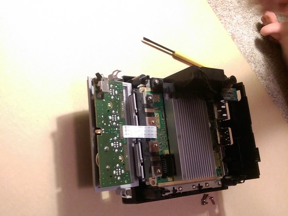
With the Optical Drive Assembly removed, your GameCube should now look like this.
-
Remove the 6 screws (circled in orange) on the heat sink using a #1 Phillips screwdriver.
-
-
Este passo não foi traduzido. Ajude a traduzi-lo
-
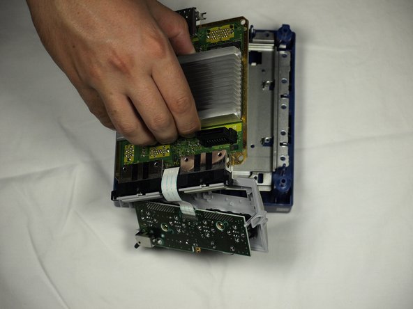
Gently lift the motherboard from base (as shown in second picture).
-
-
Este passo não foi traduzido. Ajude a traduzi-lo
-
Carefully disconnect the ribbon cable connecting the motherboard with the front panel.
-
-
Este passo não foi traduzido. Ajude a traduzi-lo
-
Locate the R5 and R6 pads.
-
They are situated to the right of where the heat sink's back middle screw was. If you are working with an American system (like me), the R5 pads will be empty. On a Japanese console, R6 will be empty.
-
-
Este passo não foi traduzido. Ajude a traduzi-lo
-
Solder the wires to either side of the empty pad (R5 for American consoles, R6 for Japanese).
-
-
Este passo não foi traduzido. Ajude a traduzi-lo
-
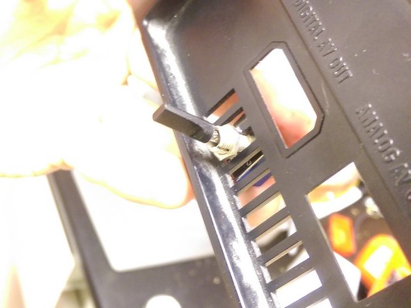
Insert the switch. In this example, a slot was removed from the vent to allow a larger switch. Make sure your switch is firmly attached and that its position will allow it to fit into the system.
-
-
Este passo não foi traduzido. Ajude a traduzi-lo
-
Solder the two sides from the R pads to your switch. Attach one to either middle terminal and attach the other wire to the terminal above or below the other.
-
-
Este passo não foi traduzido. Ajude a traduzi-lo
-
Reassemble. Route the new wires so that they won't be pinched during reassembly and be sure they can't get pulled.
-


Cancelar: não concluí este guia.
8 outras pessoas executaram este guia.
12 comentários
great instructions, it really works but now how do i translate the japanese game (Muscle Champion KINNIKUZIMA NO Kessen
There is no way to translate the game itself unless there’s an English option in the game somewhere.
Hello, is there any way to switch my gamecube's region from Japan to US without Soldering? I want to keep my Gamecube in US mode and have no intention of switching between the two.
Without soldering? Not really, but you don’t need to install a switch to make a permanent jump to NTSC-U (US mode). See the red text note on step 15 about how to avoid making a permanent connection. Hope this helps!