Esta versão pode conter edições incorretas. Mude para o último instantâneo verificado.
O que você precisa
-
Este passo não foi traduzido. Ajude a traduzi-lo
-
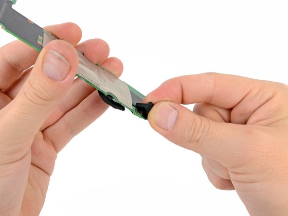
Gently insert a plastic opening tool near the top of the Nexus 7 between the rear panel and the front panel assembly.
-
Carefully run the plastic opening tool along the top edge to pry the rear panel away from the front panel assembly of the Nexus 7.
-
-
Este passo não foi traduzido. Ajude a traduzi-lo
-
Insert the plastic opening tool between the rear panel and the front panel assembly near the power button and pry up at several points along the right edge of the Nexus 7.
-
-
Este passo não foi traduzido. Ajude a traduzi-lo
-
Pry up the rear panel along the left edge using the method described in previous steps.
-
-
Este passo não foi traduzido. Ajude a traduzi-lo
-
Gently lift and remove the rear panel up off the front panel assembly.
-
-
Este passo não foi traduzido. Ajude a traduzi-lo
-
Using the tip of a spudger, push first on one side then the other to "walk" the battery cable straight out of its socket on the motherboard.
-
-
Este passo não foi traduzido. Ajude a traduzi-lo
-
Peel back the copper ESD shielding covering the bottom of the motherboard.
-
If you're just replacing the micro usb charge port, there is no need to peel back the copper heatsink like in the photo, the speaker assembly can simply be moved out of the way once unscrewed. If the speakers are to be replaced simply peel back the bottom corner to expose the speaker connection. Leave the rest of the heatsink shield alone.
-
-
-
Este passo não foi traduzido. Ajude a traduzi-lo
-
Using the tip of a spudger, push the speaker cable straight out of its socket on the motherboard.
-
-
Este passo não foi traduzido. Ajude a traduzi-lo
-
Peel back the label covering the power and volume button ZIF connector.
-
-
Este passo não foi traduzido. Ajude a traduzi-lo
-
Use the tip of a spudger to carefully flip up the retaining flap on the power and volume button ribbon cable ZIF socket.
-
Use the tip of a spudger to pull the power and volume button ribbon cable straight out of its socket.
-
-
Este passo não foi traduzido. Ajude a traduzi-lo
-
Carefully peel back the adhesive tape covering the I/O board ribbon cable socket on the motherboard.
-
-
Este passo não foi traduzido. Ajude a traduzi-lo
-
Use the tip of a spudger to carefully flip up the retaining flap on the I/O data ribbon cable ZIF socket.
-
Use the tip of a spudger to pull the I/O data ribbon cable straight out of its socket.
-
-
Este passo não foi traduzido. Ajude a traduzi-lo
-
Peel back the adhesive tape covering the display and digitizer cable sockets.
-
-
Este passo não foi traduzido. Ajude a traduzi-lo
-
Use the flat end of a spudger to pry the display data cable straight up off its socket on the motherboard.
-
-
Este passo não foi traduzido. Ajude a traduzi-lo
-
Use the flat end of a spudger to carefully flip up the retaining flaps on the digitizer ribbon cable ZIF sockets.
-
Use the tip of a spudger to pull the digitizer ribbon cable straight out of its socket.
-
-
Este passo não foi traduzido. Ajude a traduzi-lo
-
Use the tip of a spudger to remove the warranty seal stickers.
-
-
Este passo não foi traduzido. Ajude a traduzi-lo
-
Remove the following screws securing the motherboard to the metal frame:
-
Six 3.25 mm silver Phillips screws
-
One 2.23 mm black Phillips screw
-
-
Este passo não foi traduzido. Ajude a traduzi-lo
-
Carefully lift the motherboard assembly out of the Nexus 7, minding any cables that may get caught.
-
-
Este passo não foi traduzido. Ajude a traduzi-lo
-
Use the flat end of a spudger to pry the front-facing camera straight off of its socket on the motherboard.
-
-
Este passo não foi traduzido. Ajude a traduzi-lo
-
Carefully pull the upper microphone straight up off its socket.
-
In a similar fashion, remove the rubber lower microphone gasket from the motherboard.
-


Cancelar: não concluí este guia.
40 outras pessoas executaram este guia.


16 comentários
Very good guide.
When peeling back the tape in various steps, it's quite easy to tear it and the replacement motherboard I had didn't come with any new tape. I used electrical tape to secure the cables and components as they were originally and it seemed to work fine.
Additionally, since my broken unit had been unused for a while, the battery was totally dead. It took a while for it to show signs of life (left it plugged in for 30+ minutes) and I found that holding the power button and pressing the volume down button together for a few minutes also helped to bring it back into action.
How long did you need to hold down the power buttons? Literally minutes, or was it 1 min or 20 sec or something like that?
My Nexus 7 2012 sat unused for probably 6+ months. I replaced the motherboard following these directions, and have triple-checked that everything is connected correctly. The battery is getting charge--the wall plug and device feel warm when it's plugged in. However, unable to get any response out of the device. I've held all combinations of buttons (I seem to remember getting into boot mode with volume up + power) but nothing happens.
jesvanv -