Esta versão pode conter edições incorretas. Mude para o último instantâneo verificado.
O que você precisa
-
Este passo não foi traduzido. Ajude a traduzi-lo
-
Insert a SIM card ejection tool into the hole on the SIM card tray, located on the left edge of the phone.
-
Press in to eject the SIM card tray.
-
Remove the SIM card tray.
-
-
Este passo não foi traduzido. Ajude a traduzi-lo
-
Place an opening pick in the opening of the SIM card tray slot and twist it sideways to release the first plastic clip that holds the rear panel in its place.
-
Slide the opening pick around the top edge of the phone to release the plastic clips that secure the rear panel.
-
-
Este passo não foi traduzido. Ajude a traduzi-lo
-
Continue to slide the opening pick around all sides of the phone to release all clips that secure the rear panel.
-
-
Este passo não foi traduzido. Ajude a traduzi-lo
-
Tilt the opening pick to lift the rear panel a little bit.
-
There are two more plastic clips next to the fingerprint sensor. Release them by gently pulling the rear panel.
-
Remove the rear panel.
-
-
Este passo não foi traduzido. Ajude a traduzi-lo
-
Remove the ten 3.6 mm Phillips screws that secure the midframe.
-
-
Este passo não foi traduzido. Ajude a traduzi-lo
-
Insert an opening pick into the SIM card tray slot and twist the opening pick sideways to release the plastic clips.
-
-
Este passo não foi traduzido. Ajude a traduzi-lo
-
Continue sliding the opening pick around the upper part of the midframe to release the plastic clips.
-
-
Este passo não foi traduzido. Ajude a traduzi-lo
-
Use the plastic pick to pry open the plastic clips on the long edge of the midframe and on the bottom edge.
-
-
Este passo não foi traduzido. Ajude a traduzi-lo
-
Make sure all the clips are free.
-
Carefully remove the midframe.
-
-
-
Este passo não foi traduzido. Ajude a traduzi-lo
-
Use the edge of a spudger to pry up and disconnect the battery flex cable located at the bottom right of the motherboard.
-
-
Este passo não foi traduzido. Ajude a traduzi-lo
-
Use an iOpener to loosen the adhesive beneath the battery. Apply the iOpener on the back of the phone for at least two minutes.
-
-
Este passo não foi traduzido. Ajude a traduzi-lo
-
Insert the flat end of a spudger under the bottom left corner of the battery and gently pry upwards.
-
If you are having trouble prying up the battery, the adhesive may not be loose enough. You can apply some isopropyl alcohol under each corner of the battery and allow it to penetrate for several minutes to help weaken the adhesive.
-
-
Este passo não foi traduzido. Ajude a traduzi-lo
-
Insert the flat end of a spudger under the bottom right corner of the battery and gently pry upwards to loosen the remaining adhesive.
-
-
Este passo não foi traduzido. Ajude a traduzi-lo
-
Use an iOpener to loosen the adhesive beneath the rear facing camera. Place the iOpener across the top part of the phone for about 30 seconds.
-
-
Este passo não foi traduzido. Ajude a traduzi-lo
-
Apply the flat end of a spudger to the left side of the rear facing camera and carefully lever it up. Make sure all of the adhesive underneath is loosened.
-
-
Este passo não foi traduzido. Ajude a traduzi-lo
-
Use the flat end of a spudger to pry up the display flex connector.
-
-
Este passo não foi traduzido. Ajude a traduzi-lo
-
Grip the lower part of the motherboard with your fingers and carefully lift it upwards.
-
Gently pull the motherboard towards the bottom edge to free it from the plastic clip next to the rear-facing camera.
-
Carefully lift the motherboard out of the frame.
-
-
Este passo não foi traduzido. Ajude a traduzi-lo
-
Use a pair of tweezers to free the rubber feet and lift the power button upwards.
-
Remove the power button.
-
-
Este passo não foi traduzido. Ajude a traduzi-lo
-
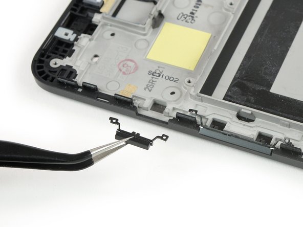
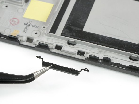
Free the rubber feet of the volume button with a pair of tweezers and lift it upwards.
-
Remove the volume button.
-
-
Este passo não foi traduzido. Ajude a traduzi-lo
-
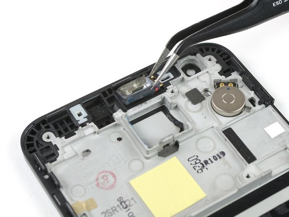
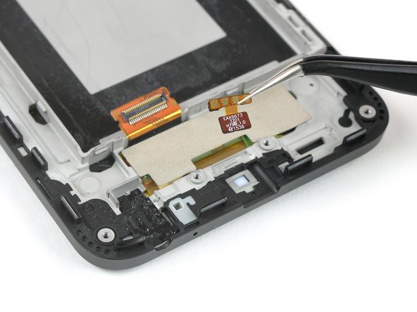
Use a pair of tweezers to gently peel of the tape that holds down the earpiece speaker.
-
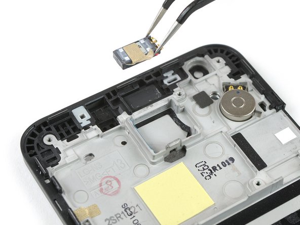
Use the tweezers to carefully lift the earpiece speaker out of its gasket.
-
Remove the earpiece speaker.
-
-
Este passo não foi traduzido. Ajude a traduzi-lo
-
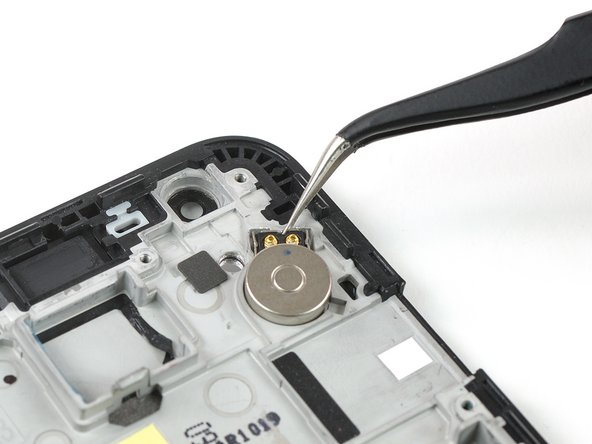
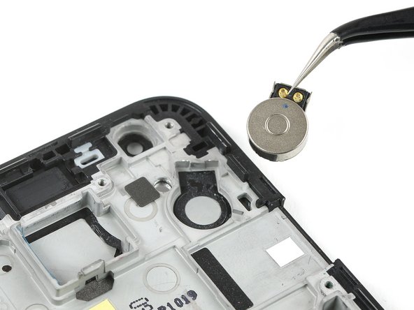
The adhesive underneath the vibration motor is strong. Use an iOpener on the top part of the screen for about 30 seconds to loosen it.
-
Use a pair of tweezers to pry up and remove the vibration motor.
-
-
Este passo não foi traduzido. Ajude a traduzi-lo
-
Insert the pointy end of a spudger into the opening of the headphone jack.
-
Use the spudger to lever the headphone jack up and out of its gasket by pulling it upwards.
-
Remove the headphone jack.
-
-
Este passo não foi traduzido. Ajude a traduzi-lo
-
Use a pair of tweezers to gently peel off the RGB LED notification indicator.
-
Remove the RGB LED notification indicator.
-