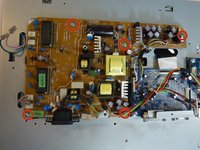
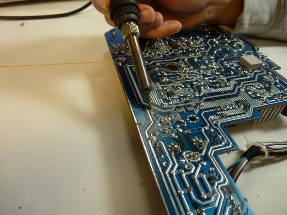
Ir para o conteúdo principal

NEC LCD1770NX Power Input Replacement

O que você precisa

  1. NEC LCD1770NX Power Input Replacement, Stand: passo 1, imagem 1 %32 NEC LCD1770NX Power Input Replacement, Stand: passo 1, imagem 2 %32
    • Place the monitor face down on a clean, flat surface.

  2. NEC LCD1770NX Power Input Replacement: passo 2, imagem 1 %32 NEC LCD1770NX Power Input Replacement: passo 2, imagem 2 %32
    • Firmly remove the back panel of the stand by pulling it up and away from the monitor.

  3. NEC LCD1770NX Power Input Replacement: passo 3, imagem 1 %32 NEC LCD1770NX Power Input Replacement: passo 3, imagem 2 %32
    • Unscrew the two 6mm Phillips PH2 screws to detach the stand enclosure from the stand.

  4. NEC LCD1770NX Power Input Replacement: passo 4, imagem 1 %32 NEC LCD1770NX Power Input Replacement: passo 4, imagem 2 %32
    • Firmly grasp the stand enclosure with your hand and slide it to base of stand.

  5. NEC LCD1770NX Power Input Replacement: passo 5, imagem 1 %32
    • Unscrew the two 14.5mm Phillips PH2 screws holding the stand to the monitor.

  6. NEC LCD1770NX Power Input Replacement: passo 6, imagem 1 %32 NEC LCD1770NX Power Input Replacement: passo 6, imagem 2 %32
    • Lift the the stand straight up to remove it.

  7. NEC LCD1770NX Power Input Replacement, Monitor Enclosure: passo 7, imagem 1 %32 NEC LCD1770NX Power Input Replacement, Monitor Enclosure: passo 7, imagem 2 %32 NEC LCD1770NX Power Input Replacement, Monitor Enclosure: passo 7, imagem 3 %32
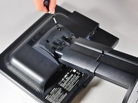
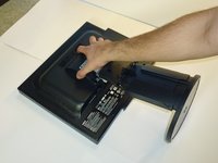
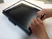
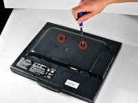
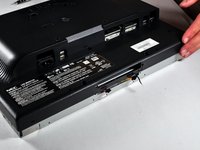
    • Place the monitor screen face up.

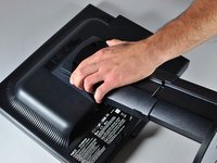
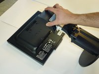
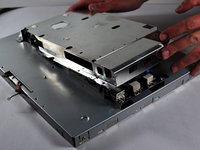
    • Pull the frame off by placing your fingers on the inside of the frame and pulling out and up, the frame should snap off.

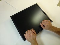
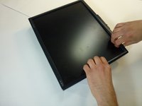
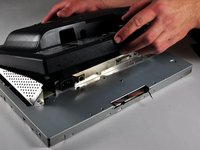
    • Continue your way around the screen.

  8. NEC LCD1770NX Power Input Replacement: passo 8, imagem 1 %32 NEC LCD1770NX Power Input Replacement: passo 8, imagem 2 %32 NEC LCD1770NX Power Input Replacement: passo 8, imagem 3 %32
    • Unscrew the two 7mm screws from the bottom of the button assembly.

    • Do not pull the button assembly out too quickly or with too much force! Damage to the wires can occur.

    • Pull the button assembly out a few inches and unplug the colored cables.

  9. NEC LCD1770NX Power Input Replacement: passo 9, imagem 1 %32 NEC LCD1770NX Power Input Replacement: passo 9, imagem 2 %32
    • Unscrew the gold colored 7mm Phillips PH000 screw holding the button assembly to the monitor.

    • Remove the button assembly from the monitor.

  10. NEC LCD1770NX Power Input Replacement: passo 10, imagem 1 %32
    • With the monitor face-down, unscrew the 5 7mm Phillips PH2 screws around the outside of the enclosure.

  11. NEC LCD1770NX Power Input Replacement: passo 11, imagem 1 %32 NEC LCD1770NX Power Input Replacement: passo 11, imagem 2 %32 NEC LCD1770NX Power Input Replacement: passo 11, imagem 3 %32
    • Unscrew the 2 14.5mm Phillips PH2 screws located on the raised center of the enclosure.

    • Carefully pull the enclosure off the monitor.

  12. NEC LCD1770NX Power Input Replacement: passo 12, imagem 1 %32 NEC LCD1770NX Power Input Replacement: passo 12, imagem 2 %32
    • Unscrew the 10 5mm Philips PH2 screws holding the metal casing to the monitor.

  13. NEC LCD1770NX Power Input Replacement: passo 13, imagem 1 %32 NEC LCD1770NX Power Input Replacement: passo 13, imagem 2 %32
    • Pull the the metal casing off of the monitor to reveal the motherboards.

  14. NEC LCD1770NX Power Input Replacement, Power Circuit Board: passo 14, imagem 1 %32 NEC LCD1770NX Power Input Replacement, Power Circuit Board: passo 14, imagem 2 %32 NEC LCD1770NX Power Input Replacement, Power Circuit Board: passo 14, imagem 3 %32
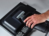
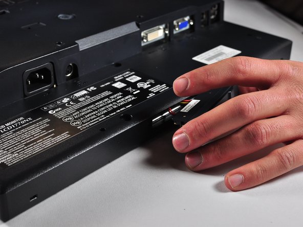
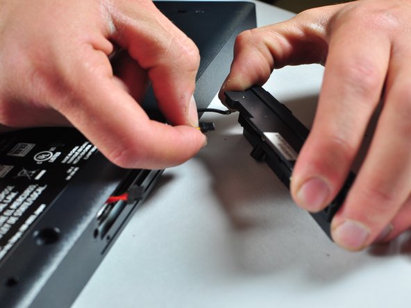
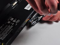
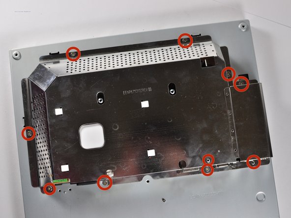
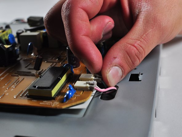
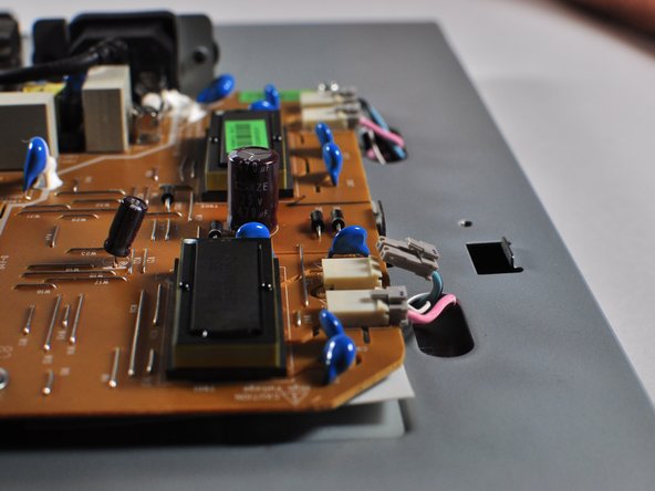
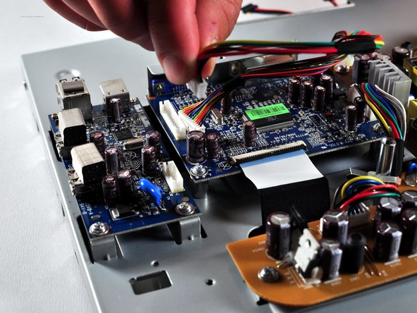
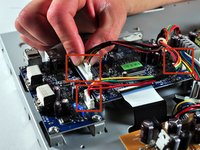
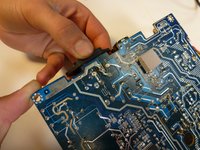
    • Make a note or use a pen to mark which plugs correspond to which colors. (Pink or Blue)

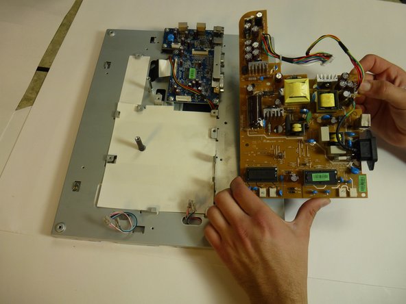
    • Remove the four plugs on the brown circuit board by pulling up on the tabs and wiggling them out. You could also use a spudger to help you lift little clips holding them in.

  15. NEC LCD1770NX Power Input Replacement: passo 15, imagem 1 %32 NEC LCD1770NX Power Input Replacement: passo 15, imagem 2 %32 NEC LCD1770NX Power Input Replacement: passo 15, imagem 3 %32
    Ferramenta utilizada nesse passo:
    Large Needle Nose Pliers
    $4.99
    Comprar
    • Locate the several multi-wire connectors on the board.

    • These connect several parts of each board together and consist of several different colors of wires. There is also a zip-tie holding the two sets of wires together that you can cut if it is getting in your way.

    • Disconnect the three plastic connectors from the blue colored boards by pulling them up while wiggling them.

    • Some force is necessary, it may also help to use the Large Needle Nose Pliers.

  16. NEC LCD1770NX Power Input Replacement: passo 16, imagem 1 %32
    Ferramenta utilizada nesse passo:
    Phillips #1 Screwdriver
    $5.49
    Comprar
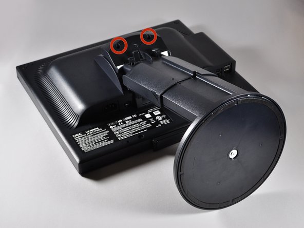
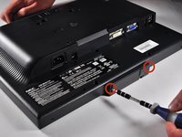
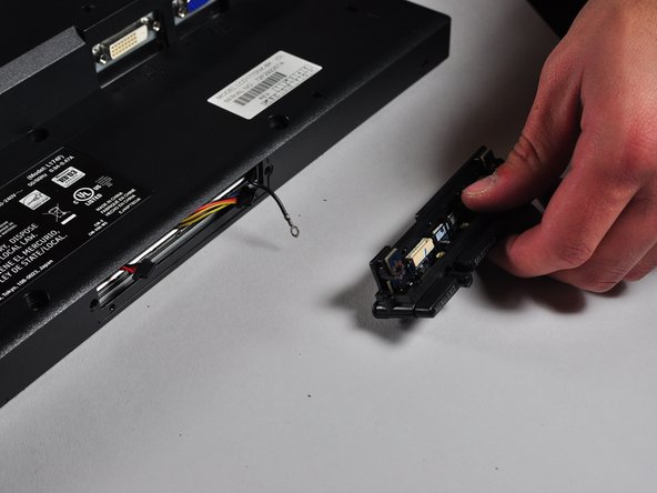
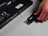
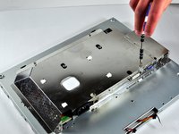
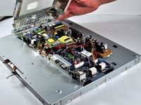
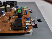
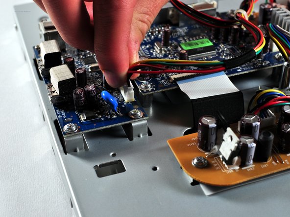
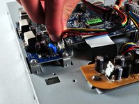
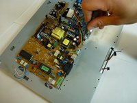
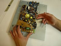
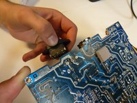
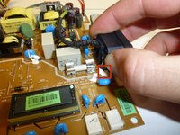
    • Locate the large black power plug.

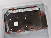
    • Using a Phillips #1 Screwdriver, unscrew the two 8mm colts holding the black tabs to the metal frame.

  17. NEC LCD1770NX Power Input Replacement: passo 17, imagem 1 %32
    • Locate and remove the gold colored 10mm Philips screw located near the black power plug. It holds in a wire that connects to the power plug.

  18. NEC LCD1770NX Power Input Replacement: passo 18, imagem 1 %32 NEC LCD1770NX Power Input Replacement: passo 18, imagem 2 %32
    • Remove 5 8mm Phillip1 screws, with a Philips 1 screwdriver, located in various places on the board.

  19. NEC LCD1770NX Power Input Replacement: passo 19, imagem 1 %32 NEC LCD1770NX Power Input Replacement: passo 19, imagem 2 %32
    • Lift the brown power supply board off of the frame and set it aside.

  20. NEC LCD1770NX Power Input Replacement, Power Input: passo 20, imagem 1 %32 NEC LCD1770NX Power Input Replacement, Power Input: passo 20, imagem 2 %32
    • Remove the solder from the three joints attached to the power input.

  21. NEC LCD1770NX Power Input Replacement: passo 21, imagem 1 %32 NEC LCD1770NX Power Input Replacement: passo 21, imagem 2 %32 NEC LCD1770NX Power Input Replacement: passo 21, imagem 3 %32
    • Grab hold of the power supply jack and remove it from the power supply board.

    • A little force and a wiggling action may be needed to remove the power supply jack from the glue.

Conclusão

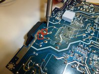
To reassemble your device, follow these instructions in reverse order.

Uma outra pessoa concluiu este guia.

Charlie Mohr

Membro desde: 10/21/13

353 Reputação

Autoria de 3 guias

Equipe

Cal Poly, Team 11-36, Amido Fall 2013 Membro de Cal Poly, Team 11-36, Amido Fall 2013

CPSU-AMIDO-F13S11G36

Membros da 5

Autoria de 7 guias

0 comentários

Adicione um comentário

Exibir estatísticas:

Últimas 24 horas: 0

Últimos 7 dias: 4

Últimos 30 dias: 14

Duração total: 1,810