Esta versão pode conter edições incorretas. Mude para o último instantâneo verificado.
O que você precisa
-
Este passo não foi traduzido. Ajude a traduzi-lo
-
Insert the SIM card eject tool into the hole in the side of the SIM card tray and push to eject the tray.
-
Remove the SIM card tray.
-
-
Este passo não foi traduzido. Ajude a traduzi-lo
-
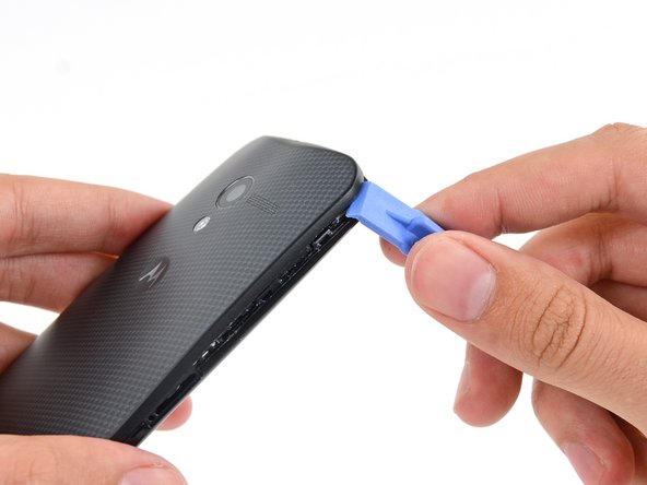
Insert a plastic opening tool into the seam between the front and rear covers near the SIM card slot.
-
Slide the plastic opening tool along the seam toward the upper corner.
-
-
Este passo não foi traduzido. Ajude a traduzi-lo
-
Carefully slide the plastic opening tool around the corner, freeing it from clips.
-
-
Este passo não foi traduzido. Ajude a traduzi-lo
-
Pry around the top right corner of the phone between the two covers.
-
-
Este passo não foi traduzido. Ajude a traduzi-lo
-
Run the opening tool along the seam around all four sides, separating the remaining clips holding the cover on.
-
-
Este passo não foi traduzido. Ajude a traduzi-lo
-
Heat an iOpener and lay it over the phone for approximately 90 seconds to loosen the adhesive securing the back cover.
-
-
Este passo não foi traduzido. Ajude a traduzi-lo
-
Starting from the SIM slot side, carefully peel the back cover off of the phone.
-
-
Este passo não foi traduzido. Ajude a traduzi-lo
-
Gently set the back cover down in a way that exposes the camera flash cable connector, but does not put strain on it.
-
-
Este passo não foi traduzido. Ajude a traduzi-lo
-
Use the tip of a spudger to flip up the retaining flap on the flash cable ZIF connector.
-
Pull the flash cable straight out of its socket.
-
-
Este passo não foi traduzido. Ajude a traduzi-lo
-
Remove the four 3 mm T3 Torx screws securing the lower antenna assembly to the phone.
-
-
Este passo não foi traduzido. Ajude a traduzi-lo
-
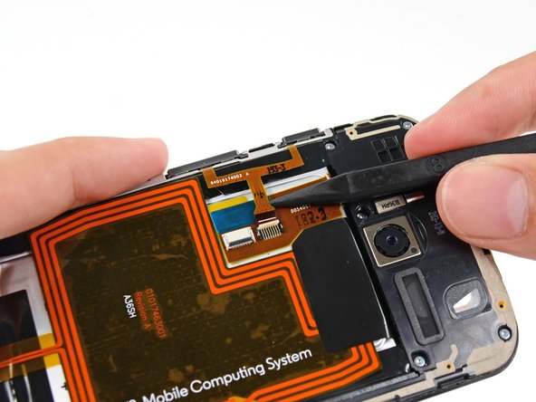
Use the flat end of a spudger to pry up the lower antenna assembly and free it from the phone.
-
Remove the antenna assembly.
-
-
-
Este passo não foi traduzido. Ajude a traduzi-lo
-
Insert the tip of a spudger under the battery cable near the connector to lift it straight up from its socket.
-
Use the flat end of a spudger to disconnect the NFC antenna cable connector.
-
-
Este passo não foi traduzido. Ajude a traduzi-lo
-
Use the tip of a spudger to flip up the ZIF retaining flap from the button assembly cable connector.
-
Slide the tip of the spudger under the button assembly cable near the connector to pull the cable straight out of its socket.
-
-
Este passo não foi traduzido. Ajude a traduzi-lo
-
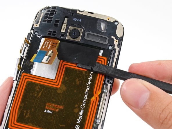
Insert the flat end of a spudger under the interconnect cable to free it from the adhesive holding it to the battery.
-
-
Este passo não foi traduzido. Ajude a traduzi-lo
-
Use the flat end of a spudger to peel the adhesive pull-tab off the top of battery.
-
-
Este passo não foi traduzido. Ajude a traduzi-lo
-
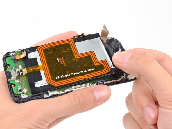
Use the adhesive pull-tab to lift the battery from its recess.
-
Remove the battery from the phone.
-
-
Este passo não foi traduzido. Ajude a traduzi-lo
-
Remove the five 3 mm T3 Torx screws from the headphone jack/speaker assembly.
-
-
Este passo não foi traduzido. Ajude a traduzi-lo
-
Insert a spudger under the panhandle of the headphone jack/speaker assembly and pry it up from its recess.
-
Remove the headphone jack/speaker assembly.
-
-
Este passo não foi traduzido. Ajude a traduzi-lo
-
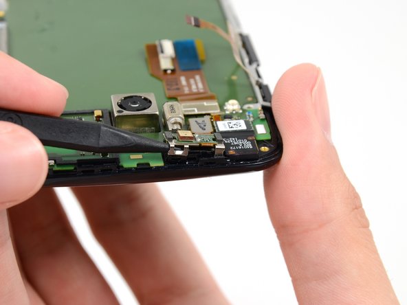
Push the tip of a spudger under the microphone assembly clip to free it from the earpiece speaker.
-
-
Este passo não foi traduzido. Ajude a traduzi-lo
-
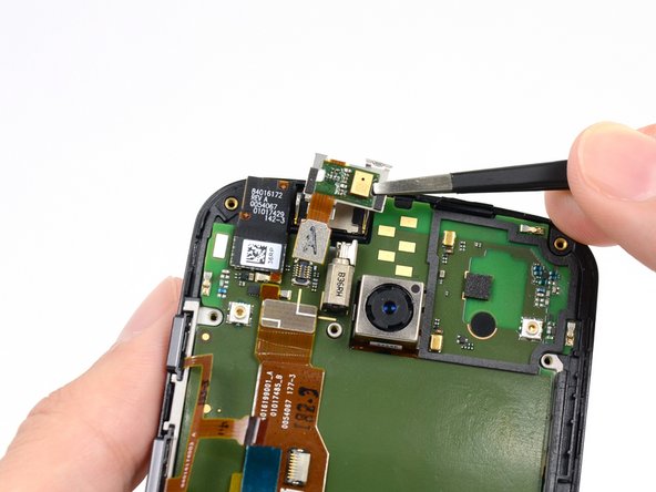
Use the flat end of a spudger to free the microphone assembly cable connector.
-
Use tweezers to remove the microphone assembly.
-
-
Este passo não foi traduzido. Ajude a traduzi-lo
-
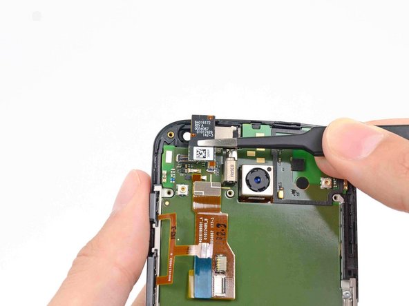
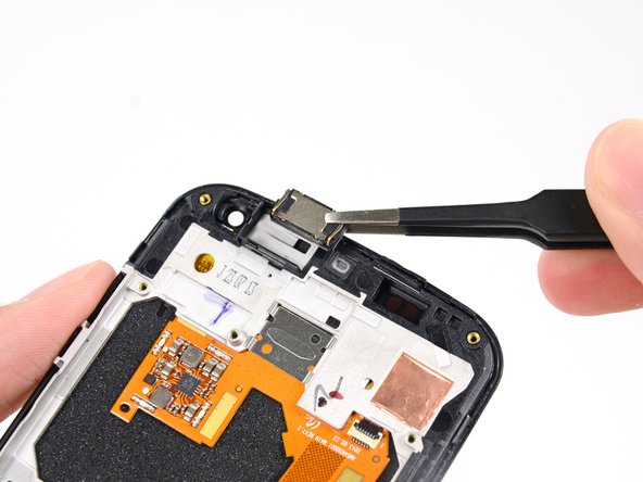
Disconnect the front-facing camera cable connector.
-
Remove the front-facing camera from its recess with a pair of tweezers.
-
-
Este passo não foi traduzido. Ajude a traduzi-lo
-
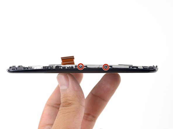
Remove the final two 3 mm T3 Torx screws from the SIM slot bracket.
-
-
Este passo não foi traduzido. Ajude a traduzi-lo
-
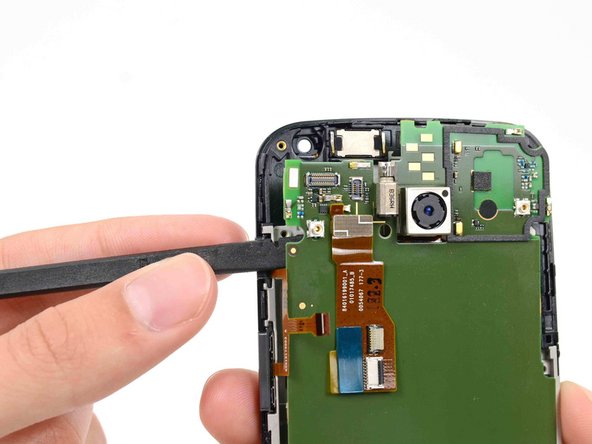
Insert the flat end of a spudger under the motherboard above the button assembly cable, and pry it out of the phone.
-
-
Este passo não foi traduzido. Ajude a traduzi-lo
-
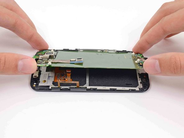
Gently lift the motherboard out of the phone, rotating it from the SIM slot edge of the phone.
-
-
Este passo não foi traduzido. Ajude a traduzi-lo
-
Use the flat end of a spudger to flip the retaining tab on the display cable ZIF connector.
-
Carefully pull the display cable out of its connector as you remove the motherboard from the display assembly.
-
-
Este passo não foi traduzido. Ajude a traduzi-lo
-
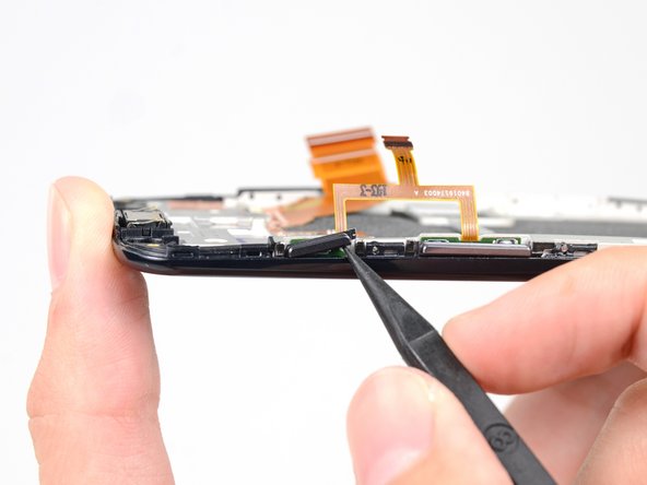
Use the tip of a spudger to nudge the sleep/power button out of its slot in the display assembly.
-
Remove the sleep/power button cover with a pair of tweezers.
-
-
Este passo não foi traduzido. Ajude a traduzi-lo
-
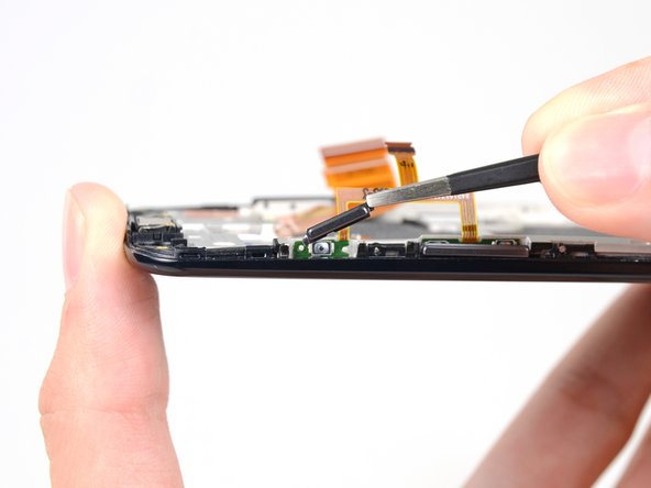
Use the tip of a spudger to push the volume rocker button cover out of the display assembly, and remove.
-
-
Este passo não foi traduzido. Ajude a traduzi-lo
-
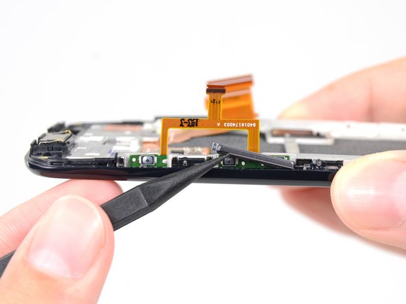
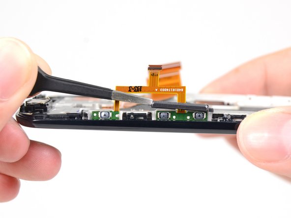
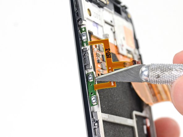
Use the tip of a hobby knife or plastic opening tool to pry the button assembly off of the adhesive securing it to the display assembly.
-
-
Este passo não foi traduzido. Ajude a traduzi-lo
-
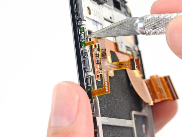
Remove the button assembly cable from the display assembly.
-
-
Este passo não foi traduzido. Ajude a traduzi-lo
-
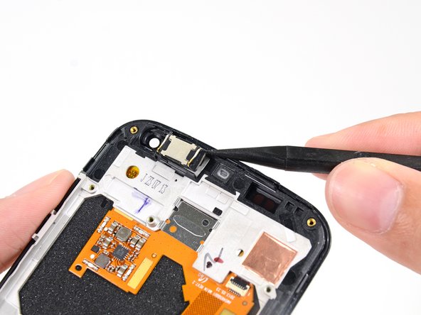
Pry the earpiece speaker out of the display assembly with the point of a spudger.
-
Remove the earpiece speaker with a pair of tweezers.
-
-
Este passo não foi traduzido. Ajude a traduzi-lo
-
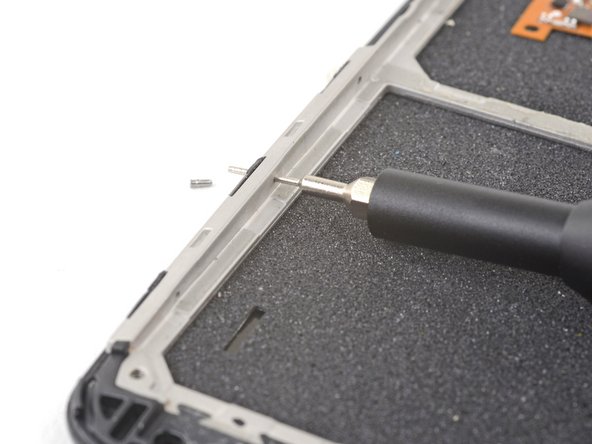
The white mid-frame is held to the display assembly by tiny pins.
-
Look over the long edges of the display assembly and note where all the pins are.
-
-
Este passo não foi traduzido. Ajude a traduzi-lo
-
Use a SIM eject tool, SIM eject bit, or a bent paper clip to gently push the pin outwards from within the case.
-
Repeat the process for the remaining pins.
-
-
Este passo não foi traduzido. Ajude a traduzi-lo
-
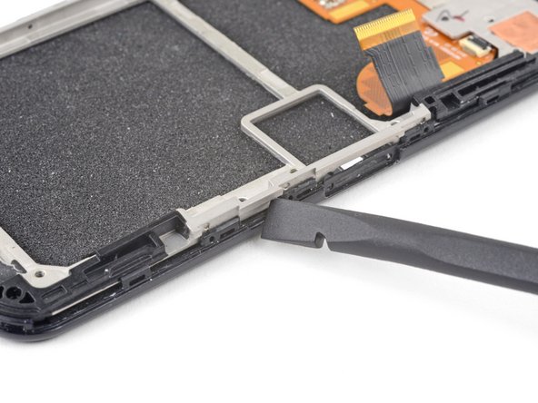
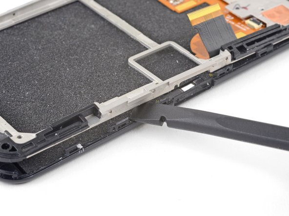
Use the flat end of a spudger to pry up the white mid-frame from the display assembly.
-
-
Este passo não foi traduzido. Ajude a traduzi-lo
-
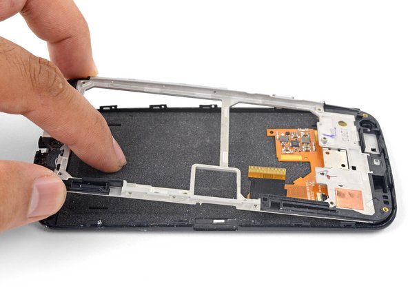
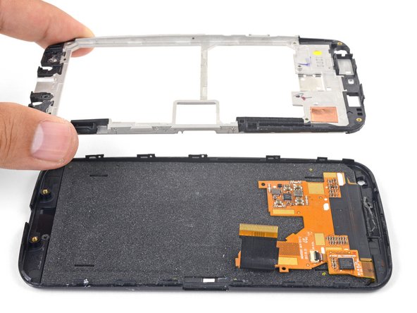
Hold the edges of the white mid-frame and push against the display assembly to swing the mid-frame free.
-
Remove the white mid-frame.
-
When reassembling your phone replace old adhesive with double-sided tape or pre-cut adhesive strips.
-


Cancelar: não concluí este guia.
61 outras pessoas executaram este guia.


20 comentários
I was able to follow this guide, but the T3 Torx was too small. The T4 Torx was also too small. Fortunately I had a T5 Torx which worked perfectly. During removal of the back I damaged my NFC antenna and can't use my Moto Skip anymore. Be careful with that component.
BUY THIS TORX SCREWDRIVER https://www.amazon.com/Husky-74502-Torx-...
NO seriously I have done a ton of electronics projects and getting a torx screwdriver that actually works with most electronics has been a struggle this is the new version of the husky 8-1 I have the old version I believe they are the same. This thing has caught thread on screws where I had given up hope
This is insane. I'm a computer tech, I build computers for a living. I repair components. Fixing this little crappy phone is crazy complex. Look at all the comments saying "be careful of x because I destroyed it accidentally". Not a one says "wow, that was incredibly simple".
I personally wouldn't try it -- I'd just get another phone and have it swapped onto my account. And then I'd stop doing whatever I'd done to break the first one.
You should leave ifixit to the qualified. Just stick to Best Buy, kid.
Brn Mace -
Ohhh Ziiingg so hot it burns!