Esta versão pode conter edições incorretas. Mude para o último instantâneo verificado.
O que você precisa
-
Este passo não foi traduzido. Ajude a traduzi-lo
-
Use a SIM eject bit, SIM eject tool, or paper clip to remove the SIM card from your phone.
-
-
Este passo não foi traduzido. Ajude a traduzi-lo
-
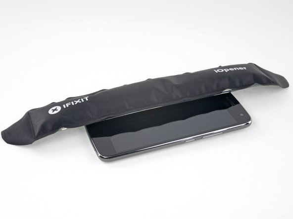
Prepare an iOpener and heat the front of the phone along its left edge for about two minutes, or until it's slightly too hot to touch. This will help soften the adhesive securing the display.
-
-
Este passo não foi traduzido. Ajude a traduzi-lo
-
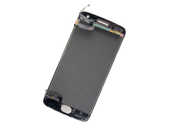
Refer to the second and third images and familiarize yourself with the width of the adhesive around edges of the display.
-
-
Este passo não foi traduzido. Ajude a traduzi-lo
-
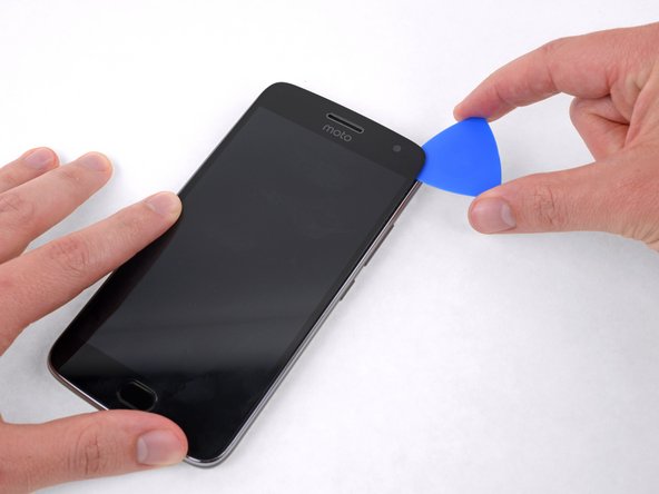
Apply a suction cup to the display, near the middle of the left edge.
-
Pull the suction cup with firm, constant pressure to create a slight gap between the display panel and the rear case.
-
If the display doesn't separate even with significant force, apply more heat to further soften the adhesive and try again. The adhesive cools quickly, so you may need to heat it repeatedly.
-
-
Este passo não foi traduzido. Ajude a traduzi-lo
-
Slide the tool along the left edge of the phone, cutting through the adhesive securing the display.
-
-
Este passo não foi traduzido. Ajude a traduzi-lo
-
Slide the opening pick down and cut the adhesive around the bottom of the display.
-
-
-
Este passo não foi traduzido. Ajude a traduzi-lo
-
Continue cutting through the adhesive on the top and right sides of the phone.
-
-
Este passo não foi traduzido. Ajude a traduzi-lo
-
Once all the adhesive is cut, carefully lift open the display from the left edge.
-
Prop the display unit at a 90 degree angle against a box to prevent the display and fingerprint cables from bending or tearing.
-
-
Este passo não foi traduzido. Ajude a traduzi-lo
-
Remove the yellow sticker covering two of the black Phillips screws below the earpiece.
-
-
Este passo não foi traduzido. Ajude a traduzi-lo
-
Remove the following Phillips screws from the midframe:
-
Sixteen 3.8 mm black screws
-
Three 2.4 mm silver screws
-
-
Este passo não foi traduzido. Ajude a traduzi-lo
-
Insert the flat end of a spudger between the midframe and the left edge of the phone and carefully pry to release the two clips holding the midframe in place.
-
-
Este passo não foi traduzido. Ajude a traduzi-lo
-
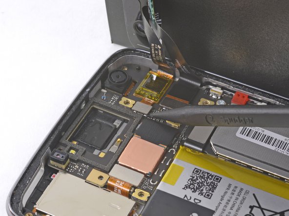
Use the point of a spudger to disconnect the larger of the two display cable connectors.
-
-
Este passo não foi traduzido. Ajude a traduzi-lo
-
Disconnect the smaller display cable connector.
-
Gently continue lifting the cable to break the adhesive seal and pull the cable away from the motherboard.
-
-
Este passo não foi traduzido. Ajude a traduzi-lo
-
At the opposite end of the phone, disconnect the fingerprint sensor cable.
-


Cancelar: não concluí este guia.
37 outras pessoas executaram este guia.

20 comentários
Thank you for the explainations. I followed the whole tutorial and I manage to fix the phone with no surprise.
Thank you. Instructions are great.
After replacing the screen, touch is offset by 125 pixels on Y axis (meaning that first registration from the top edge is at 125 px). Is there a way to get the phone to recalibrate?
Thanks
Thanks. These tips, plus the Moto G5 LCD guide solved my problem. The replacement I purchased was only for the LCD (needed to heat and remove the glass after disassembling the whole phone). Again, thanks.
does the silver plastic on back of digitizer need to be removed in order for the screen to light up on the display??
I assume there are two pieces to the screen - the glass front/digitizer/touchscreen and the LCD display itself. Is this correct? On mine I believe only the glass/digitizer is cracked since the phone works fine and has only a minor crack. This tutorial doesn’t show how to separate them. Is my understanding correct? I also need to buy the correct part and it is a bit confusing.