Esta versão pode conter edições incorretas. Mude para o último instantâneo verificado.
O que você precisa
-
Este passo não foi traduzido. Ajude a traduzi-lo
-
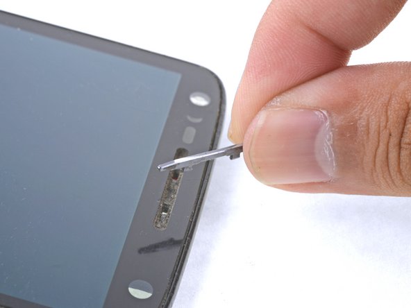
Insert a SIM eject tool, SIM eject bit, or a straightened paperclip into the small hole in the SIM card tray.
-
Press to eject the tray.
-
Remove the SIM card tray assembly from the phone.
-
-
Este passo não foi traduzido. Ajude a traduzi-lo
-
Heat an iOpener and apply it to the top edge of the phone for a minute.
-
-
Este passo não foi traduzido. Ajude a traduzi-lo
-
Angle an opening pick and firmly press so that it slips under the back cover.
-
-
Este passo não foi traduzido. Ajude a traduzi-lo
-
Slide the opening pick along the top edge of the phone to break up the adhesive.
-
Use the pick to release the deeper areas but avoid slicing through the camera bezel area.
-
-
Este passo não foi traduzido. Ajude a traduzi-lo
-
Repeat the iOpener heating and slicing procedures for the remaining three sides.
-
-
Este passo não foi traduzido. Ajude a traduzi-lo
-
Once you have cut through the adhesive, slowly peel the back cover away from the frame.
-
Remove the back cover.
-
-
Este passo não foi traduzido. Ajude a traduzi-lo
-
Insert an opening pick under the flash connector rubber cover and pry forward to remove it.
-
-
Este passo não foi traduzido. Ajude a traduzi-lo
-
Use the point of a spudger to pry up and remove the coil connector rubber cover.
-
To reinstall the cover, align the cover and use your finger to push it forward into place.
-
-
Este passo não foi traduzido. Ajude a traduzi-lo
-
Use the point of a spudger to pry up and disconnect the flash connector.
-
-
Este passo não foi traduzido. Ajude a traduzi-lo
-
Use the point of a spudger to pry up and disconnect the wireless charging coil connector.
-
-
Este passo não foi traduzido. Ajude a traduzi-lo
-
Remove the following T3 screws securing the midframe:
-
Thirteen 3.1 mm black screws
-
Four 4.3 mm silver screws
-
-
-
Este passo não foi traduzido. Ajude a traduzi-lo
-
Insert an opening pick along the frame seam and twist slightly to release the midframe from the phone.
-
-
Este passo não foi traduzido. Ajude a traduzi-lo
-
Carefully peel the black graphite layer from the phone.
-
-
Este passo não foi traduzido. Ajude a traduzi-lo
-
Remove the two 4.2 mm T3 screws securing the metal bracket adjacent to the battery.
-
Remove the metal bracket.
-
-
Este passo não foi traduzido. Ajude a traduzi-lo
-
Use the point of a spudger to pry up and disconnect the battery pack connector.
-
-
Este passo não foi traduzido. Ajude a traduzi-lo
-
Angle and insert an opening pick under the long edge of the battery away from the motherboard side.
-
Insert a second opening pick along the same battery edge next to the first pick.
-
-
Este passo não foi traduzido. Ajude a traduzi-lo
-
Apply firm, constant prying pressure to the picks to release the battery from the frame.
-
As the battery loosens from the frame, move the picks inward and continue to pry upwards.
-
-
Este passo não foi traduzido. Ajude a traduzi-lo
-
Remove the battery.
-
To help with alignment, connect the battery temporarily to the motherboard before adhering it in place. Disconnect the battery before you continue with re-assembly.
-
-
Este passo não foi traduzido. Ajude a traduzi-lo
-
Insert an opening pick underneath the flat flex cable and slide it to free the cable from the frame.
-
-
Este passo não foi traduzido. Ajude a traduzi-lo
-
Use the point of a spudger to pry up and disconnect the antenna cable.
-
De-route the antenna cable from the phone.
-
-
Este passo não foi traduzido. Ajude a traduzi-lo
-
Use the flat end of a spudger to pry up and disconnect the accessory module connector.
-
-
Este passo não foi traduzido. Ajude a traduzi-lo
-
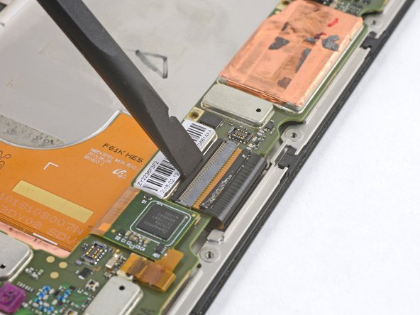
Peel away the yellow tape covering the display ZIF connector.
-
Use the flat end of a spudger to gently flip up the ZIF connector lock.
-
-
Este passo não foi traduzido. Ajude a traduzi-lo
-
Use a spudger or tweezers to walk the flat cable out of the ZIF connector.
-
-
Este passo não foi traduzido. Ajude a traduzi-lo
-
Peel away the yellow tape covering the digitizer ZIF connector.
-
Use the point of a spudger to flip up the ZIF connector lock.
-
-
Este passo não foi traduzido. Ajude a traduzi-lo
-
Use tweezers or a spudger to walk the ribbon cable out of the ZIF connector.
-
-
Este passo não foi traduzido. Ajude a traduzi-lo
-
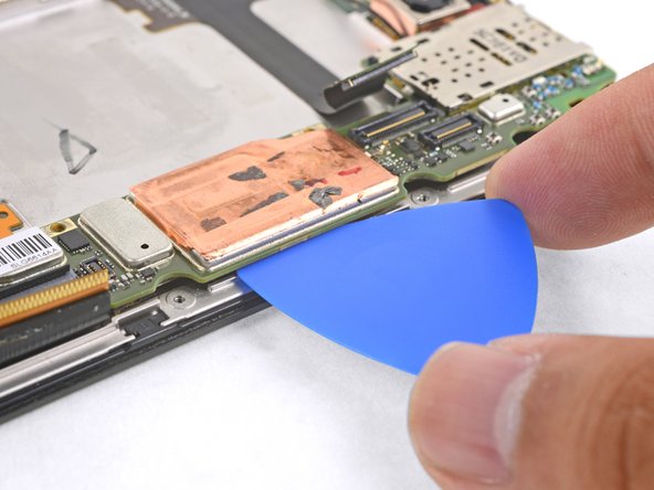
Slide an opening pick underneath the motherboard below the copper shield.
-
Twist the pick slightly to release the adhesive tape securing the motherboard to the frame.
-
-
Este passo não foi traduzido. Ajude a traduzi-lo
-
Lift the motherboard out, making sure it does not catch on any cables.
-
Remove the motherboard.
-
-
Este passo não foi traduzido. Ajude a traduzi-lo
-
Use the flat end of a spudger to pry up and disconnect the front facing camera connector.
-
Remove and transfer the front facing camera onto the new display frame.
-
-
Este passo não foi traduzido. Ajude a traduzi-lo
-
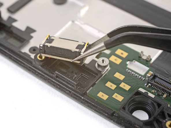
Insert a pointed end of a pair of tweezers into a corner as far down as possible.
-
Pry very slightly to help loosen the earpiece speaker module.
-
Repeat the process in the remaining corners.
-
-
Este passo não foi traduzido. Ajude a traduzi-lo
-
Continue to pry with the point of a pair of tweezers until the earpiece module feels loose.
-
Remove the earpiece module and transfer it to the new display frame.
-
-
Este passo não foi traduzido. Ajude a traduzi-lo
-
Use the point of a spudger to pry up and remove the speaker grille cover.
-
Remove and transfer the speaker grille cover onto the new display frame.
-
-
Este passo não foi traduzido. Ajude a traduzi-lo
-
Only the LCD screen and digitizer assembly (with frame) should remain.
-
Compare your new replacement part to the original part. You may need to transfer remaining components or remove adhesive backings from the new part before installing.
-


Cancelar: não concluí este guia.
6 outras pessoas executaram este guia.

