Esta versão pode conter edições incorretas. Mude para o último instantâneo verificado.
O que você precisa
-
Este passo não foi traduzido. Ajude a traduzi-lo
-
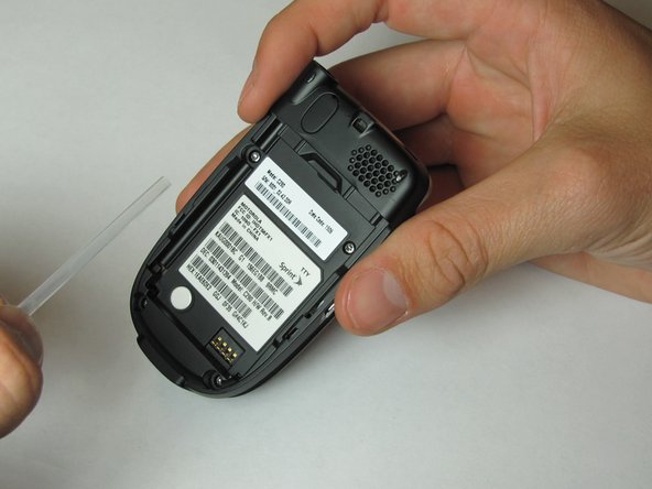
Position Motorola C290 so that the back of the phone is facing up.
-
Apply pressure to the back cover while simultaneously sliding it downwards.
-
-
Este passo não foi traduzido. Ajude a traduzi-lo
-
Place your finger in the notch at the top of the battery.
-
Gently lift and pull out battery.
-
-
Este passo não foi traduzido. Ajude a traduzi-lo
-
Unscrew antenna head from top of phone by twisting counterclockwise.
-
Pull the antenna out through the top hole and set aside.
-
-
Este passo não foi traduzido. Ajude a traduzi-lo
-
Remove the plastic tube by lifting the bottom and pulling out towards yourself.
-
-
-
Este passo não foi traduzido. Ajude a traduzi-lo
-
Insert a Spudger (or pushpin) into the top notch of the rubber cover, located on the top of the phone.
-
Press down and rotate the Spudger lifting the rubber cover. Remove and set cover aside.
-
Using a T6 Torx screwdriver, unscrew all 5 screws and carefully set them aside.
-
-
Este passo não foi traduzido. Ajude a traduzi-lo
-
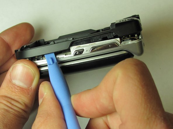
Insert the plastic opening tool in the groove at the top of the phone.
-
Rotate the tool to create an opening between the logic board cover and case.
-
-
Este passo não foi traduzido. Ajude a traduzi-lo
-
Slide the plastic opening tool along the groove, until the entire logic board cover has been opened.
-
Remove logic board cover and set aside.
-
-
Este passo não foi traduzido. Ajude a traduzi-lo
-
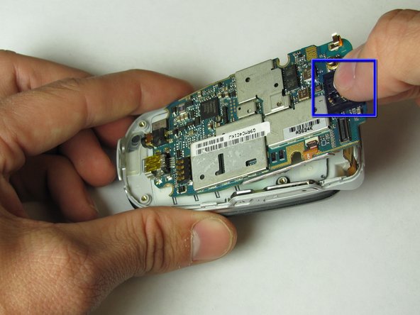
Use the Spudger to detach the screen wire from the logic board.
-
-
Este passo não foi traduzido. Ajude a traduzi-lo
-
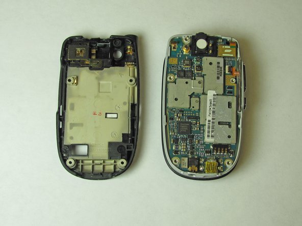
Insert the Spudger into the slot on the top of the logic board.
-
Gently pry to loosen the top of the logic board.
-
Grab the top of the logic board and pull at an angle to remove.
-


Equipe

Cal Poly, Team 24-28, Regan Spring 2010 Membro de Cal Poly, Team 24-28, Regan Spring 2010
CPSU-REGAN-S10S24G28
Membros da 4
Autoria de 6 guias