Esta versão pode conter edições incorretas. Mude para o último instantâneo verificado.
O que você precisa
-
Este passo não foi traduzido. Ajude a traduzi-lo
-
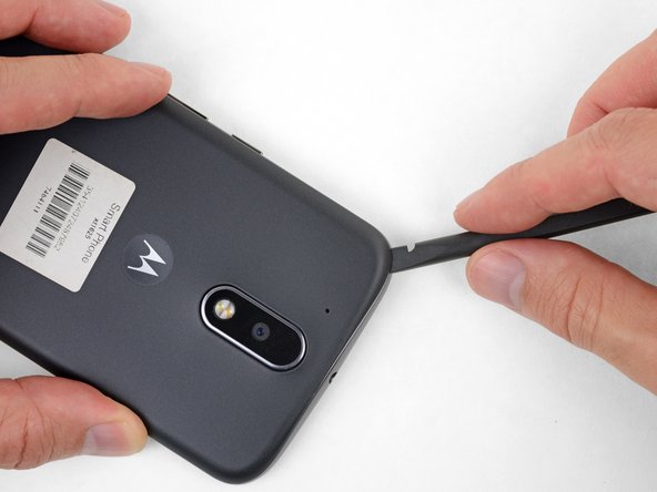
Insert a fingernail or a spudger into the notch on the bottom edge of the phone, near the charge port.
-
Gently twist or pry to open a small gap between the back cover and the body of the phone.
-
While keeping your tool (or fingernail) inserted into the gap between the back cover and the body of the phone, slide it around the corner to begin loosening the plastic clips holding the cover in place.
-
-
Este passo não foi traduzido. Ajude a traduzi-lo
-
Slide your tool all along the side of the phone to separate more of the clips securing the back cover.
-
-
Este passo não foi traduzido. Ajude a traduzi-lo
-
Keep your tool inserted slightly under the back cover, and slide it around the top corner.
-
If necessary, continue prying around the remaining edges of the phone until the back cover comes free.
-
-
Este passo não foi traduzido. Ajude a traduzi-lo
-
Push to eject and remove the MicroSD and SIM cards (if installed).
-
-
-
Este passo não foi traduzido. Ajude a traduzi-lo
-
Use a spudger to pry up the rubber cover for the camera flash connector.
-
-
Este passo não foi traduzido. Ajude a traduzi-lo
-
Use a spudger to disconnect the camera flash connector by prying it straight up.
-
-
Este passo não foi traduzido. Ajude a traduzi-lo
-
Use a T3 Torx driver to remove the nineteen identical 3.1 mm screws securing the midframe.
-
-
Este passo não foi traduzido. Ajude a traduzi-lo
-
Insert a spudger under the midframe at the top left corner, and gently twist to separate it from the body of the phone.
-
-
Este passo não foi traduzido. Ajude a traduzi-lo
-
Insert a thin tool (such as one of your tweezer tips) under the red and black battery wires, and slide it underneath the battery connector.
-
Gently pry straight up to disconnect the battery.
-
-
Este passo não foi traduzido. Ajude a traduzi-lo
-
Pull black flap on bottom of motherboard back.
-
Use tweezers to pop vibration motor off of motherboard.
-


Cancelar: não concluí este guia.
Uma outra pessoa concluiu este guia.

Equipe

USF Tampa, Team S15-G3, Boczar Spring 2018 Membro de USF Tampa, Team S15-G3, Boczar Spring 2018
USFT-BOCZAR-S18S15G3
Membros da 4
Autoria de 12 guias