Esta versão pode conter edições incorretas. Mude para o último instantâneo verificado.
O que você precisa
-
Este passo não foi traduzido. Ajude a traduzi-lo
-
Remove the plastic screw cover located on the bottom of the device. Insert a small flat-headed screwdriver into one side of the cover and gently ease it out. Repeat on the other side.
-
You will need a #00 Phillips screwdriver to remove the two 2.6 mm screws that are exposed.
-
-
Este passo não foi traduzido. Ajude a traduzi-lo
-
Use the blue plastic opening tool to slowly work your way around the edges of the case, releasing the front plate from the bottom case.
-
-
Este passo não foi traduzido. Ajude a traduzi-lo
-
Turn the Zune over so the screen faces downward. This will ensure the battery does not fall out and pull on the cable.
-
Pry up from the bottom of the Zune because the headphone jack will not allow you to remove the back case in one pull. You must slide the case up and away from the rest of the Zune.
-
-
Este passo não foi traduzido. Ajude a traduzi-lo
-
Use the small flat head screw driver to gently lift the brown clamp.
-
The clamp will release the battery ribbon cable from the logic board, freeing the battery.
-
-
Este passo não foi traduzido. Ajude a traduzi-lo
-
Now the back cover is off and the battery is removed, so the hard drive is clearly visible.
-
There are four 4.2 mm screws securing the hard drive to the logic board.
-
Remove all four screws using a Phillips #00 screwdriver.
-
-
-
Este passo não foi traduzido. Ajude a traduzi-lo
-
Carefully tilt the hard drive up from the logic board.
-
-
Este passo não foi traduzido. Ajude a traduzi-lo
-
Flip the hard drive over the top to expose the ribbon cable.
-
-
Este passo não foi traduzido. Ajude a traduzi-lo
-
The ribbon cable is held in place by a black latch on the hard drive.
-
Using a small flat head screwdriver, flip the black latch up 90 degrees.
-
-
Este passo não foi traduzido. Ajude a traduzi-lo
-
Carefully detach the ribbon cable from the hard drive.
-
Now you have completely detached the hard drive.
-
-
Este passo não foi traduzido. Ajude a traduzi-lo
-
The ribbon cable for the button sensor pad is attached with a small clamp to the bottom left corner of the logic board.
-
Use a small flathead screwdriver to lift the brown clasp and remove the ribbon cable.
-
-
Este passo não foi traduzido. Ajude a traduzi-lo
-
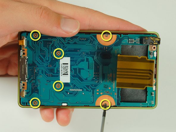
With a Philips #00 screwdriver, remove the six 4.2 mm screws that attach the logic board to the front plate.
-
-
Este passo não foi traduzido. Ajude a traduzi-lo
-
Carefully lift the logic board off of the front plate.
-
The logic board is now free.
-
Follow the LCD repair guide to detach LCD display from logic board.
-
-
Este passo não foi traduzido. Ajude a traduzi-lo
-
The LCD screen is held onto the logic board by four plastic clips. Unhook the clips with a small flathead screwdriver or your fingers.
-
-
Este passo não foi traduzido. Ajude a traduzi-lo
-
Pry up the black tab on the clamp with a small flathead screwdriver or spudger.
-
The LCD screen can now be removed.
-


Cancelar: não concluí este guia.
7 outras pessoas executaram este guia.

Um comentário
Do you know where I can get a new screen for model number 1091.