Esta versão pode conter edições incorretas. Mude para o último instantâneo verificado.
O que você precisa
-
Este passo não foi traduzido. Ajude a traduzi-lo
-
Remove the four rubber caps from the back by using the Phillips #00 screwdriver.
-
-
Este passo não foi traduzido. Ajude a traduzi-lo
-
Remove the four screws holding the cover in place by using the Phillips #00 screwdriver.
-
-
Este passo não foi traduzido. Ajude a traduzi-lo
-
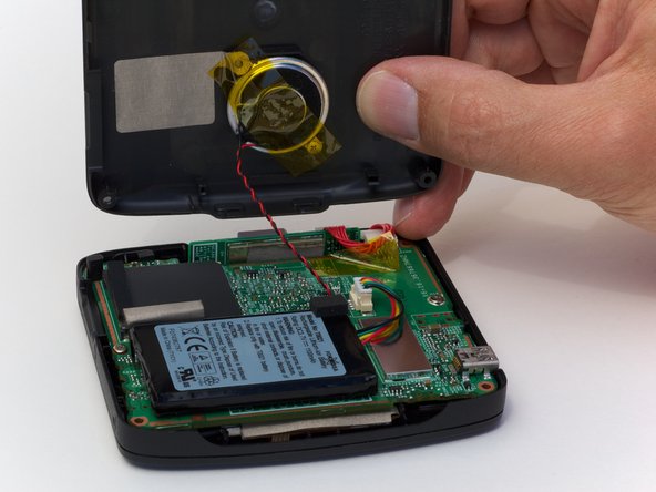
Remove the back cover from the device by separating the back cover along its seam.
-
-
Este passo não foi traduzido. Ajude a traduzi-lo
-
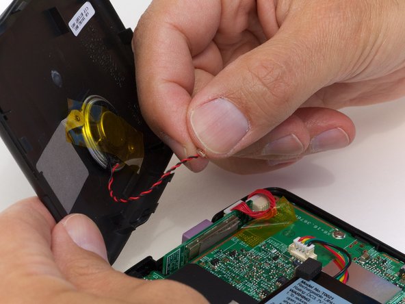
Pull the speaker cord, horizontally, by its base, away from the motherboard.
-
-
-
Este passo não foi traduzido. Ajude a traduzi-lo
-
Remove the two screws on that are located on opposite sides of the board.
-
-
Este passo não foi traduzido. Ajude a traduzi-lo
-
Lift up the circuit board and disconnect the GPS wire, pulling horizontally from its connector port.
-
-
Este passo não foi traduzido. Ajude a traduzi-lo
-
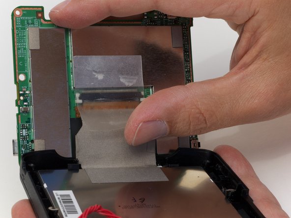
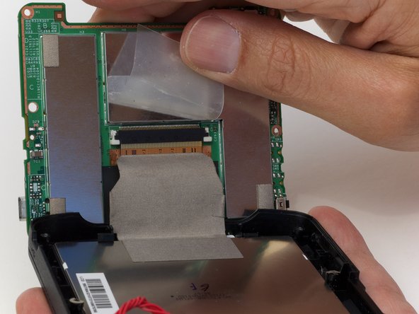
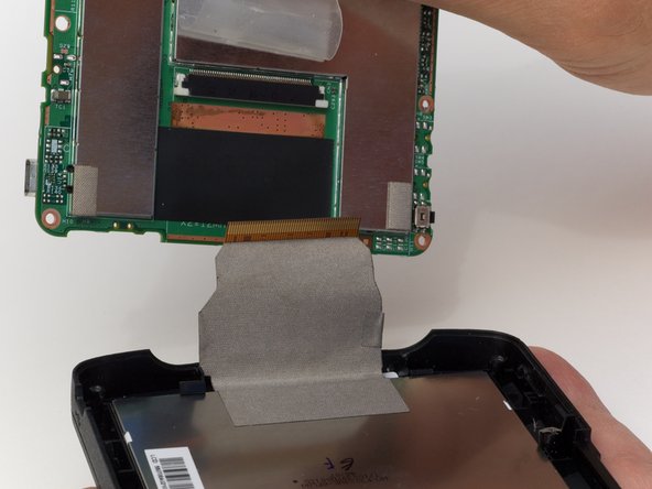
Peel back the tape securing the display connector to the logic board.
-
-
Este passo não foi traduzido. Ajude a traduzi-lo
-
Carefully flip the circuit board out so you can get to the sensor easily.
-
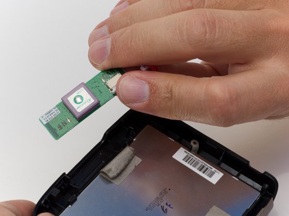
Remove the tape holding the sensor to the display and take out the sensor.
-
-
Este passo não foi traduzido. Ajude a traduzi-lo
-
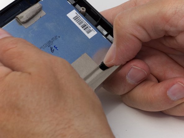
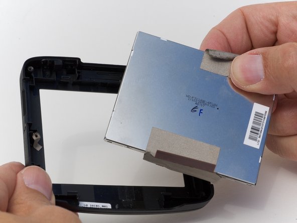
Undo the 4 clasps holding the display in place.
-
Pop the display from the front cover.
-


Cancelar: não concluí este guia.
Uma outra pessoa concluiu este guia.

Um comentário
In order to remove the rubber plugs hiding the 4 screws, I found that a straight pin angled into the top of the plug can be used to lift them easily straight out and the plug is unharmed.
With the screws out, the back did not budge. I used the thinest blade screw driver in my jeweler's set to pry the case open and pushed on the plastic catches, one on each side that were holding it closed. They are visible in the photo of the back off.