Esta versão pode conter edições incorretas. Mude para o último instantâneo verificado.
O que você precisa
-
Este passo não foi traduzido. Ajude a traduzi-lo
-
Start by turning the computer around, and remove this #0 Phillips Screw.
-
-
Este passo não foi traduzido. Ajude a traduzi-lo
-
Now lift these two clips, and slowly pivot the case up.
-
You can now seperate the top of the computer from the rest of the machine.
-
-
-
Este passo não foi traduzido. Ajude a traduzi-lo
-
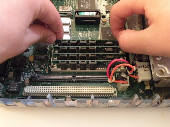
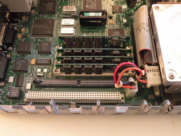
The IIsi uses 4 30-Pin SIMMs (Installed in pairs of 2) for a maximum ram capacity of 65MB. It has 1MB soldered to the logic board as well.
-
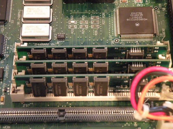
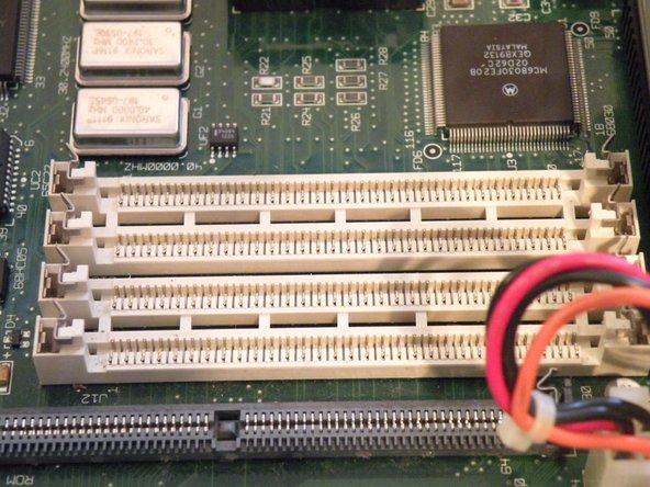
Start with this SIMM. Push these 2 metal tabs outward, then push the ram forward. It can then be lifted out. You have to remove the SIMMs in order, starting with the one you just removed. You can then work your way through all of them.
-


Cancelar: não concluí este guia.
4 outras pessoas executaram este guia.

Equipe
