Esta versão pode conter edições incorretas. Mude para o último instantâneo verificado.
O que você precisa
-
-
Ligue o Mac e abra o Terminal.
-
Copie e cole o seguinte comando (ou digite-o de forma exata) no Terminal:
-
sudo nvram AutoBoot=%00
-
Pressione [return]. Se solicitado, digite sua senha de administrador e pressione [return] novamente. ''Observação: sua tecla Return também pode se chamar ⏎ ou "enter".
-
sudo nvram AutoBoot=%03
-
-
Este passo não foi traduzido. Ajude a traduzi-lo
-
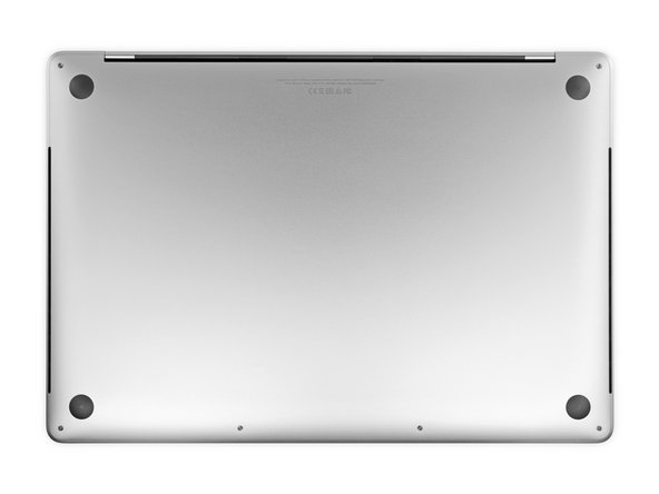
Use a P5 Pentalobe driver to remove six screws securing the lower case, of the following lengths:
-
Four 3.7 mm screws
-
Two 7.3 mm screws
-
-
Este passo não foi traduzido. Ajude a traduzi-lo
-
Press a suction handle into place near the front edge of the lower case, between the screw holes.
-
Pull up on the suction handle just enough to open a small gap under the lower case.
-
-
Este passo não foi traduzido. Ajude a traduzi-lo
-
Slide the corner of an opening pick into the gap you just created underneath the lower case.
-
Slide the opening pick around the nearest corner and then halfway up the side of the MacBook Pro.
-
-
Este passo não foi traduzido. Ajude a traduzi-lo
-
Repeat the previous step on the other side, using an opening pick to to release the second clip.
-
-
Este passo não foi traduzido. Ajude a traduzi-lo
-
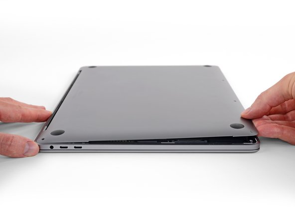
Lift the front edge of the lower case (the side opposite the display hinge) enough to slide your fingertips underneath and get a good grip on it.
-
-
Este passo não foi traduzido. Ajude a traduzi-lo
-
Pull firmly to slide the lower case towards the front edge of the MacBook (away from the hinge area) to separate the last of the clips securing the lower case.
-
Pull first at one corner, then the other.
-
-
Este passo não foi traduzido. Ajude a traduzi-lo
-
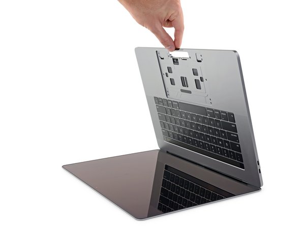
Remove the lower case.
-
Set it in place and align the sliding clips near the display hinge. Press down and slide the cover toward the hinge. It should stop sliding as the clips engage.
-
When the sliding clips are fully engaged and the lower case looks correctly aligned, press down firmly on the lower case to engage the four hidden clips underneath. You should feel and hear them snap into place.
-
-
Este passo não foi traduzido. Ajude a traduzi-lo
-
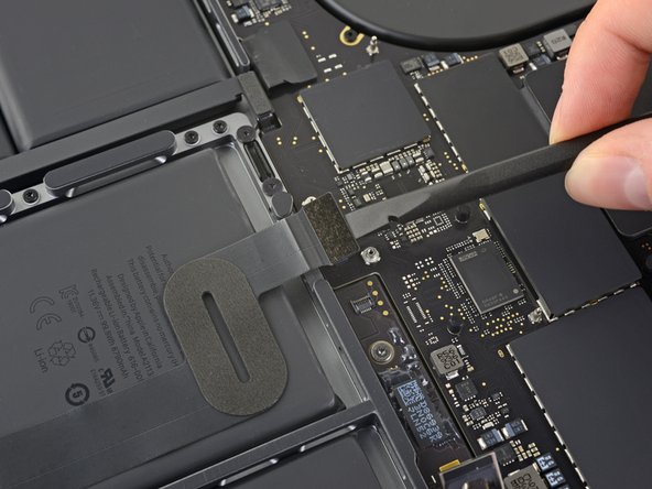
Peel up and remove the insulating sticker covering the battery board, on the edge of the logic board nearest the battery.
-
If the cover doesn't peel up easily, apply mild heat with an iOpener, hair dryer, or heat gun to soften the adhesive underneath, and try again.
-
-
Este passo não foi traduzido. Ajude a traduzi-lo
-
Peel back any tape covering the battery board data cable connector.
-
-
Este passo não foi traduzido. Ajude a traduzi-lo
-
Use a spudger to gently pry up the locking flap on the ZIF connector for the battery board data cable.
-
-
Este passo não foi traduzido. Ajude a traduzi-lo
-
Disconnect the battery board data cable by sliding it out from its socket on the logic board.
-
-
Este passo não foi traduzido. Ajude a traduzi-lo
-
Peel back any tape covering the battery board data cable connector.
-
Pry up and disconnect the locking flap on the connector at the opposite end of the battery board data cable.
-
-
Este passo não foi traduzido. Ajude a traduzi-lo
-
Slide the battery board data cable out of its socket on the battery board, and remove it completely.
-
-
Este passo não foi traduzido. Ajude a traduzi-lo
-
Use a T5 Torx driver to remove the 6.7 mm pancake screw securing the battery power connector.
-
-
Este passo não foi traduzido. Ajude a traduzi-lo
-
Use a spudger to lift the battery power connector, disconnecting the battery.
-
-
Este passo não foi traduzido. Ajude a traduzi-lo
-
Use a T3 Torx driver to remove the two 1.8 mm screws securing the cover bracket for the keyboard and trackpad cable connectors.
-
Remove the bracket.
-
-
Este passo não foi traduzido. Ajude a traduzi-lo
-
Use a spudger to disconnect the trackpad cable by prying its connector straight up from the logic board.
-
-
Este passo não foi traduzido. Ajude a traduzi-lo
-
Apply mild heat to the trackpad ribbon cable to soften the adhesive securing it to the battery.
-
-
Este passo não foi traduzido. Ajude a traduzi-lo
-
Carefully peel the trackpad cable up off the battery, and push it out of the way.
-
-
Este passo não foi traduzido. Ajude a traduzi-lo
-
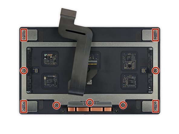
Use a T5 Torx driver to remove the 13 screws securing the trackpad assembly:
-
Nine 5.8 mm screws
-
Four 4.9 mm screws
-
-
Este passo não foi traduzido. Ajude a traduzi-lo
-
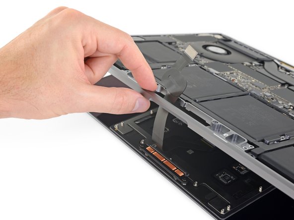
Swing the display open slightly, but keep the MacBook upside-down. The trackpad assembly should separate and lay flat on the display.
-
Carefully feed the trackpad's ribbon cable through its slot in the chassis.
-
-
Este passo não foi traduzido. Ajude a traduzi-lo
-
As you remove the trackpad assembly, be very careful not to lose the nine small metal washers resting on the screw posts. (They will fly off and get lost with very little provocation.)
-
Remove the trackpad assembly.
-
-
Este passo não foi traduzido. Ajude a traduzi-lo
-
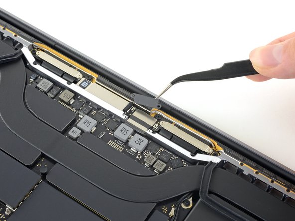
Use a T3 Torx driver to remove the two 3.5 mm screws securing the cover on the display board flex cable.
-
Remove the display board flex cover.
-
-
Este passo não foi traduzido. Ajude a traduzi-lo
-
Using a T3 Torx driver, remove the two 1.6 mm screws securing the bracket for the display board cable connector.
-
Remove the display board cable connector bracket.
-
-
Este passo não foi traduzido. Ajude a traduzi-lo
-
Pry the display board flex cable straight up from its socket to disconnect it from the display board.
-
-
Este passo não foi traduzido. Ajude a traduzi-lo
-
Use a T3 Torx driver to remove the four 2.0 mm screws from the hinge covers (two screws on each side).
-
-
-
Este passo não foi traduzido. Ajude a traduzi-lo
-
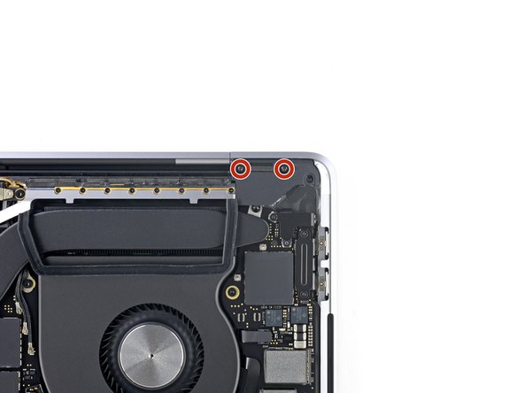
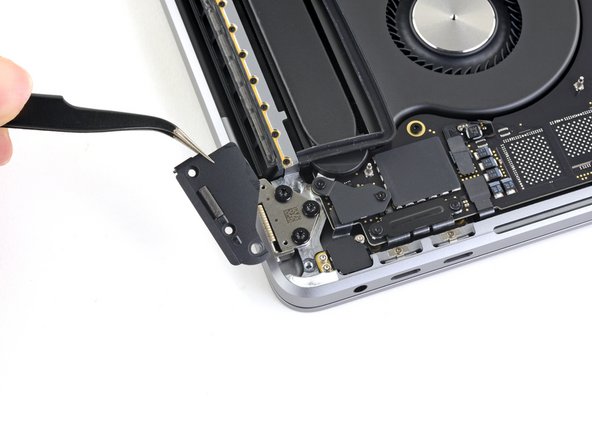
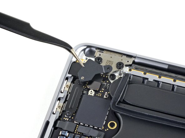
Use a T3 Torx driver to remove the two 2.4 mm screws securing the cover bracket for the Touch ID and headphone jack cable connectors.
-
Remove the bracket.
-
-
Este passo não foi traduzido. Ajude a traduzi-lo
-
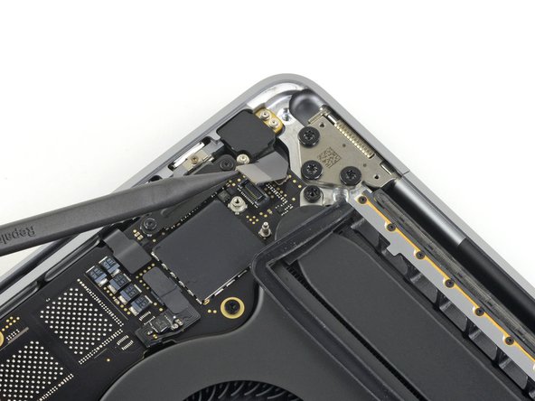
Disconnect the headphone jack flex connector by prying it straight up from the logic board.
-
-
Este passo não foi traduzido. Ajude a traduzi-lo
-
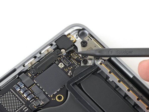
Disconnect the power button and Touch ID sensor by prying its connector straight up from the logic board.
-
-
Este passo não foi traduzido. Ajude a traduzi-lo
-
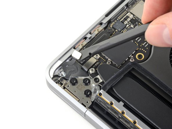
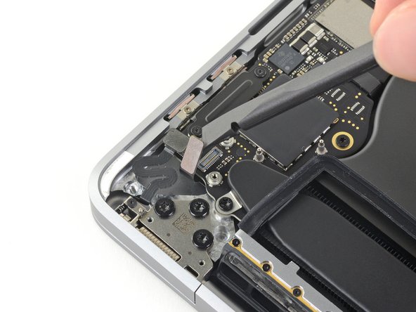
Using a T3 Torx driver, remove the two 1.5 mm screws securing the cover bracket for the Touch Bar digitizer and lid angle sensor connectors.
-
-
Este passo não foi traduzido. Ajude a traduzi-lo
-
Using your tweezers, slide the bracket toward the side edge of the MacBook Pro until it clears the slotted retaining tab on the logic board.
-
Remove the bracket.
-
-
Este passo não foi traduzido. Ajude a traduzi-lo
-
Disconnect the lid angle sensor cable by prying it straight up from the logic board.
-
Disconnect the Touch Bar digitizer cable by prying it straight up from the logic board.
-
-
Este passo não foi traduzido. Ajude a traduzi-lo
-
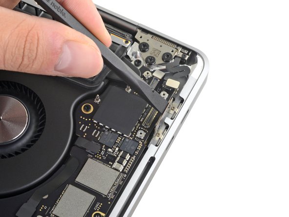
Use a T3 Torx driver to remove the two 1.9 mm screws securing the bracket for the Touch Bar display cable connector.
-
Remove the bracket.
-
-
Este passo não foi traduzido. Ajude a traduzi-lo
-
Disconnect the Touch Bar display cable by prying its connector straight up from the logic board.
-
-
Este passo não foi traduzido. Ajude a traduzi-lo
-
Using a T3 Torx Driver:
-
Remove the two 1.3 mm screws securing the Thunderbolt flex cable cover on the left.
-
Remove two more 1.3 mm screws from the Thunderbolt cable cover on the right.
-
-
Este passo não foi traduzido. Ajude a traduzi-lo
-
Remove the cover brackets from both Thunderbolt cable sockets.
-
-
Este passo não foi traduzido. Ajude a traduzi-lo
-
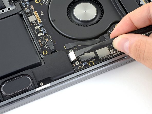
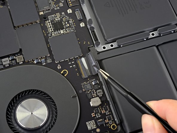
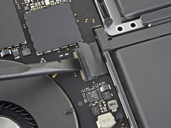
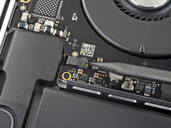
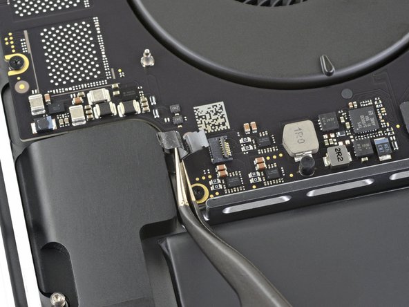
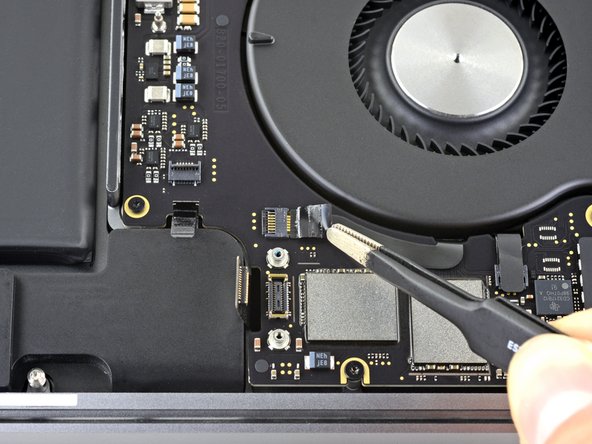
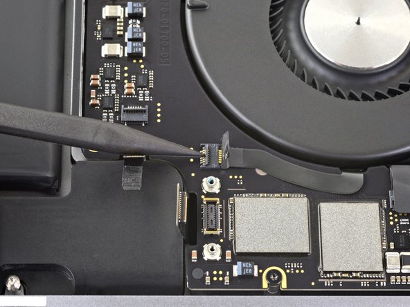
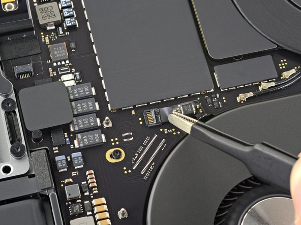
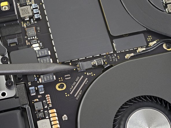
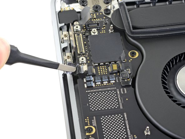
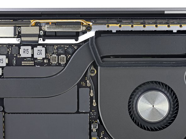
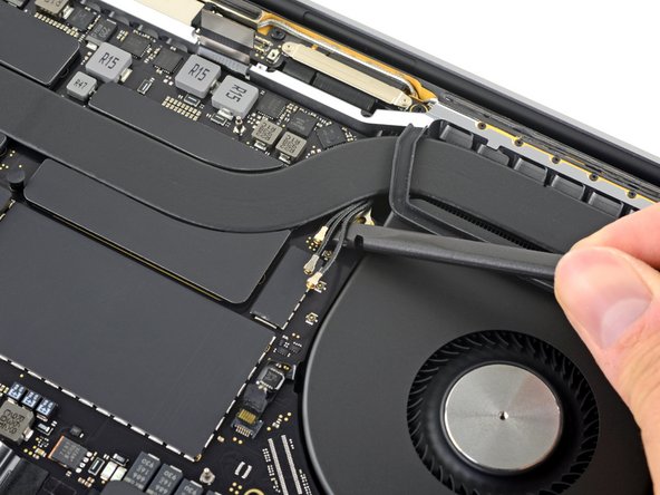
Use a spudger to disconnect the left-side Thunderbolt flex cable by prying it straight up from the logic board.
-
Pry from the inside edge, nearest the fan.
-
Gently push the flex cable connector off to the side so it doesn't interfere with logic board removal.
-
-
Este passo não foi traduzido. Ajude a traduzi-lo
-
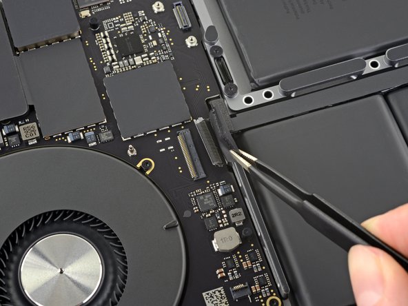
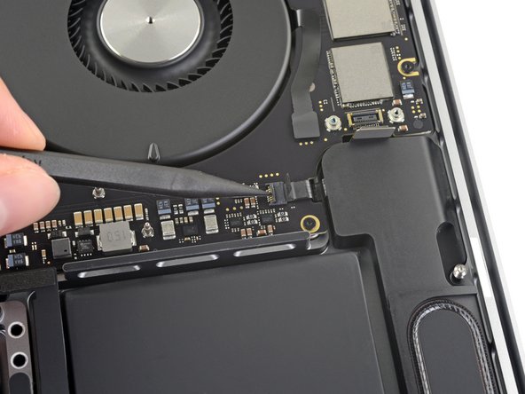
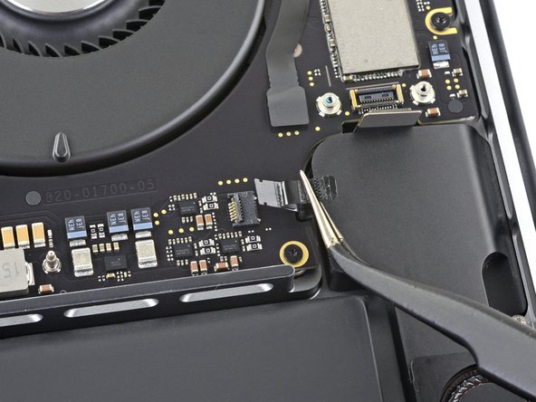
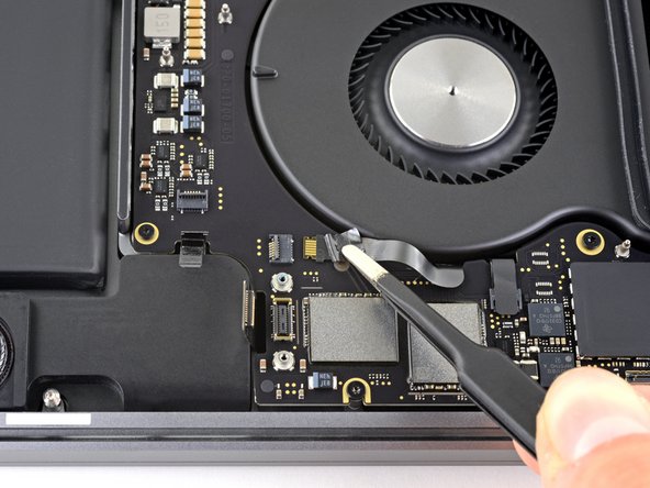
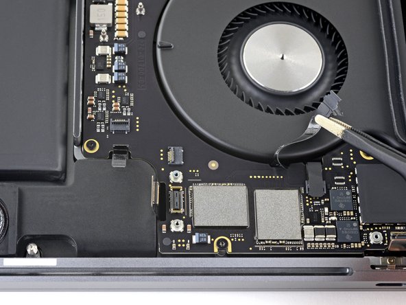
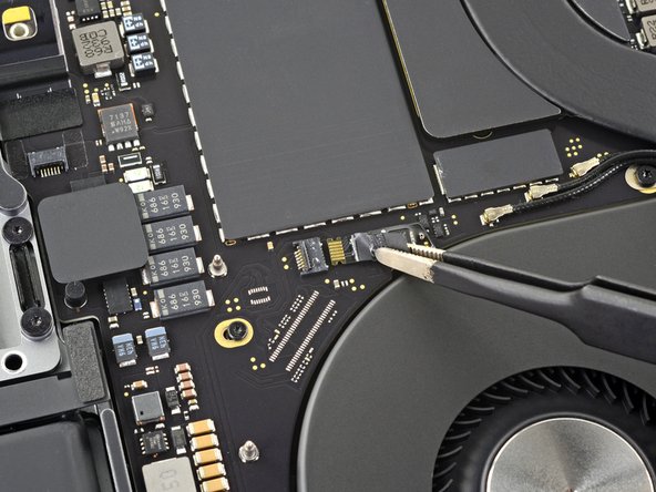
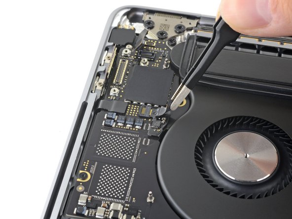
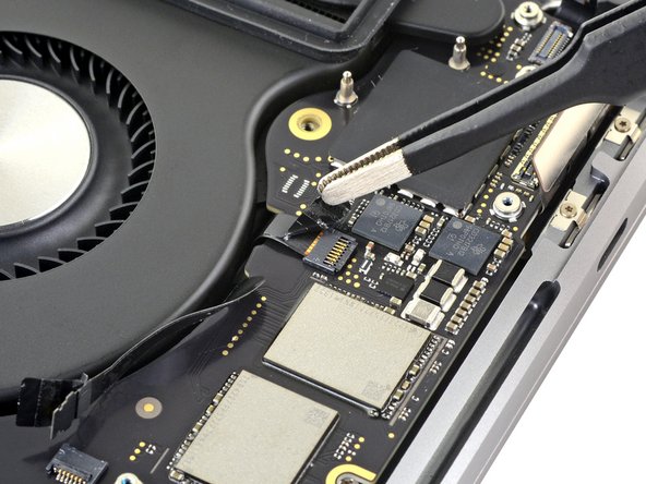
Repeat to disconnect the Thunderbolt flex cable connector on the opposite side.
-
Carefully push the flex cable connector aside so there's clearance for the logic board to come out without snagging.
-
-
Este passo não foi traduzido. Ajude a traduzi-lo
-
Peel back the tape covering the keyboard cable connector.
-
-
Este passo não foi traduzido. Ajude a traduzi-lo
-
Use a spudger to gently pry straight up on the long locking flap on the ZIF connector for the keyboard cable.
-
-
Este passo não foi traduzido. Ajude a traduzi-lo
-
Disconnect the keyboard cable by sliding it out from its socket on the logic board.
-
Pull in the direction of the cable.
-
If possible, pull on the tape attached to the cable, rather than the cable itself, to reduce the risk of damage.
-
-
Este passo não foi traduzido. Ajude a traduzi-lo
-
Peel back any tape covering the left speaker cable connector.
-
-
Este passo não foi traduzido. Ajude a traduzi-lo
-
Open the locking flap on the left speaker cable's ZIF connector by prying it straight up from the logic board.
-
-
Este passo não foi traduzido. Ajude a traduzi-lo
-
Disconnect the left speaker by pulling its cable away from the logic board until it releases from its socket.
-
If possible, pull on the tape attached to the cable, rather than the cable itself, to reduce the risk of damage.
-
-
Este passo não foi traduzido. Ajude a traduzi-lo
-
Peel back any tape covering the right speaker cable connector.
-
-
Este passo não foi traduzido. Ajude a traduzi-lo
-
Open the locking flap on the right speaker cable's ZIF connector by prying it straight up from the logic board.
-
-
Este passo não foi traduzido. Ajude a traduzi-lo
-
Disconnect the right speaker by pulling its cable away from the logic board until it releases from its socket.
-
If possible, pull on the tape attached to the cable, rather than the cable itself, to reduce the risk of damage.
-
-
Este passo não foi traduzido. Ajude a traduzi-lo
-
Peel back any tape covering the first keyboard backlight cable connector.
-
-
Este passo não foi traduzido. Ajude a traduzi-lo
-
Open the locking flap on the keyboard backlight's ZIF connector by prying it straight up from the logic board.
-
-
Este passo não foi traduzido. Ajude a traduzi-lo
-
Disconnect the keyboard backlight by pulling its cable away from the logic board until it releases from its socket.
-
If possible, pull on the tape attached to the cable, rather than the cable itself, to reduce the risk of damage.
-
Move the cable away from its connector so it can more easily clear the logic board during removal.
-
-
Este passo não foi traduzido. Ajude a traduzi-lo
-
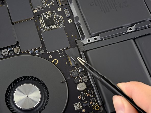
Peel back any tape covering the right fan connector.
-
-
Este passo não foi traduzido. Ajude a traduzi-lo
-
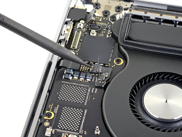
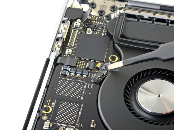
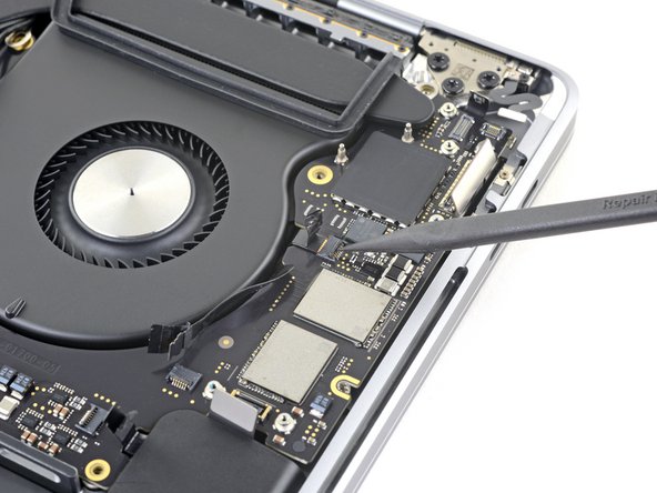
Open the locking flap on the right fan's ZIF connector by prying it straight up from the logic board.
-
Disconnect the right fan by pulling its cable away from the logic board until it releases from its socket.
-
If possible, pull on the tape attached to the cable, rather than the cable itself, to reduce the risk of damage.
-
-
Este passo não foi traduzido. Ajude a traduzi-lo
-
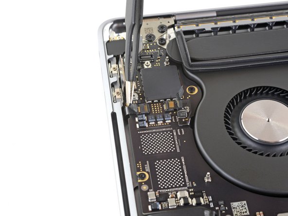
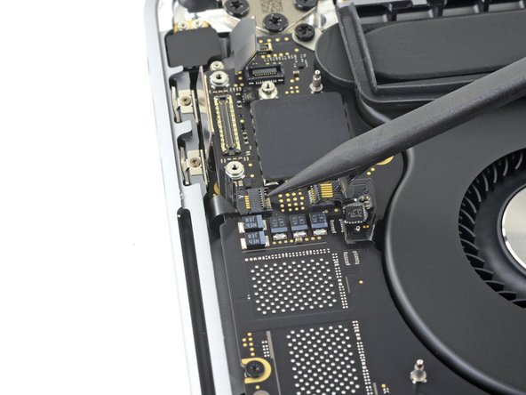
Peel back any tape covering the left fan connector.
-
-
Este passo não foi traduzido. Ajude a traduzi-lo
-
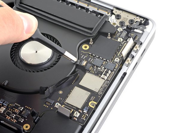
Open the locking flap on the left fan's ZIF connector by prying it straight up from the logic board.
-
Disconnect the left fan by pulling its cable away from the logic board until it releases from its socket.
-
If possible, pull on the tape attached to the cable, rather than the cable itself, to reduce the risk of damage.
-
-
Este passo não foi traduzido. Ajude a traduzi-lo
-
Peel back any tape covering the other keyboard backlight connector.
-
-
Este passo não foi traduzido. Ajude a traduzi-lo
-
Open the locking flap on the keyboard backlight's ZIF connector by prying it straight up from the logic board.
-
Disconnect the keyboard backlight by pulling its cable away from the logic board until it releases from its socket.
-
If possible, pull on the tape attached to the cable, rather than the cable itself, to reduce the risk of damage.
-
-
Este passo não foi traduzido. Ajude a traduzi-lo
-
Peel back any tape covering the microphone array connector.
-
-
Este passo não foi traduzido. Ajude a traduzi-lo
-
Open the locking flap on the microphone array's ZIF connector by prying it straight up from the logic board.
-
Disconnect the microphone array by pulling its cable away from the logic board until it releases from its socket.
-
If possible, pull on the tape attached to the cable, rather than the cable itself, to reduce the risk of damage.
-
-
Este passo não foi traduzido. Ajude a traduzi-lo
-
Use a T5 Torx driver to remove the single 2.9 mm screw securing the antenna cable bundle.
-
-
Este passo não foi traduzido. Ajude a traduzi-lo
-
Disconnect all three antenna cables by prying each one straight up from its socket.
-
Slide your tweezers or the flat end of your spudger underneath each cable until it's near the socket, and then gently twist or pry up to disconnect it.
-
-
Este passo não foi traduzido. Ajude a traduzi-lo
-
Remove all eleven screws securing the logic board assembly:
-
Three 3.3 mm T3 Torx screws
-
Two 3.6 mm T5 Torx screws
-
Four 2.9 mm T5 Torx screws
-
One 4.0 mm T8 Torx screw
-
One 4.0 mm T8 Torx screw (large head)
-
-
Este passo não foi traduzido. Ajude a traduzi-lo
-
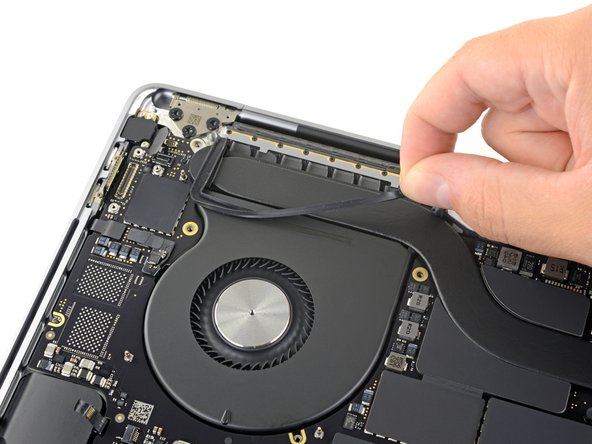
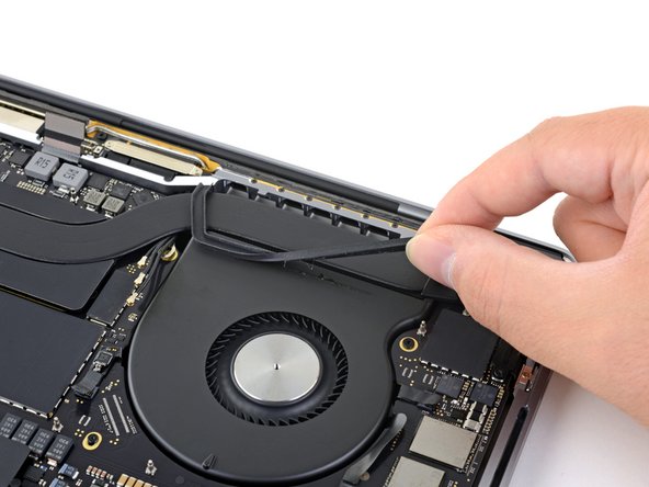
Peel up (but don't remove) the rubber vibration damping strip from the adhesive holding it to the fan.
-
If needed, apply mild heat with an iOpener, hair dryer, or heat gun to soften the adhesive and make the dampers easier to separate.
-
Repeat for the other adhesive strip on the opposite fan.
-
-
Este passo não foi traduzido. Ajude a traduzi-lo
-
Lifting from the left side, remove the logic board.
-
-
Este passo não foi traduzido. Ajude a traduzi-lo
-
Feed the antenna cable bundle through the gap between the logic board and heat sink, and make sure it lines up correctly as you lower the board into place.
-
Verify that no cables get trapped under the board as you install it. Check each of the fifteen marked locations carefully.
-
-
Este passo não foi traduzido. Ajude a traduzi-lo
-
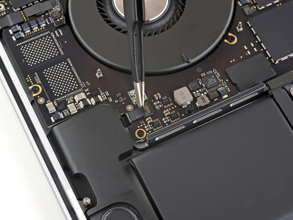
Use a T5 Torx driver to remove the 5.1 mm screw securing the battery board.
-
-
Este passo não foi traduzido. Ajude a traduzi-lo
-
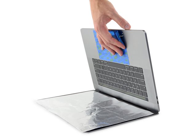
To protect your display, place a sheet of aluminum foil between the display and keyboard and leave it there while you work.
-
Additionally, use painter's tape to seal off the area under the trackpad as best you can. Optionally, you may also layer an absorbent towel directly underneath the trackpad area to soak up any excess adhesive remover.
-
-
Este passo não foi traduzido. Ajude a traduzi-lo
-
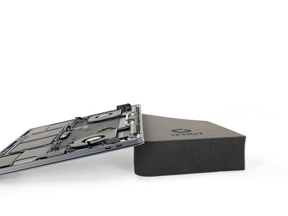
To control the flow of adhesive remover, raise the back edge (hinge side) of your MacBook Pro a few inches using a book or foam block.
-
-
Este passo não foi traduzido. Ajude a traduzi-lo
-
Now that your MacBook Pro is fully prepped, it's time to prep yourself.
-
Wear eye protection when handling and applying the adhesive remover. (Eye protection is included in your kit.)
-
Do not wear contact lenses without eye protection.
-
Protective gloves are also included in your kit. If you are concerned about possible skin irritation, put your gloves on now.
-
-
Este passo não foi traduzido. Ajude a traduzi-lo
-
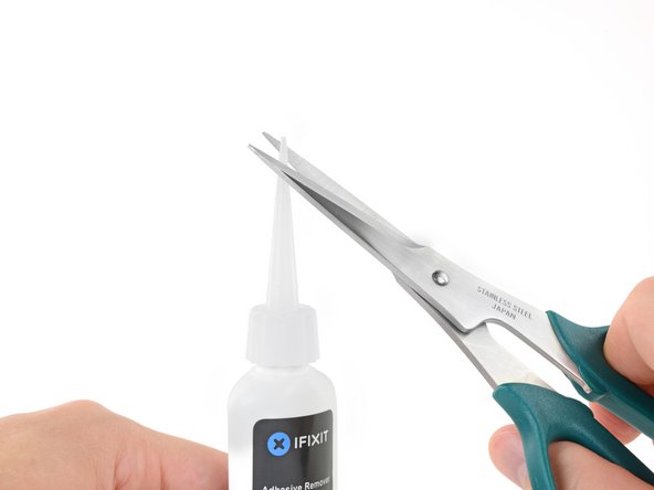
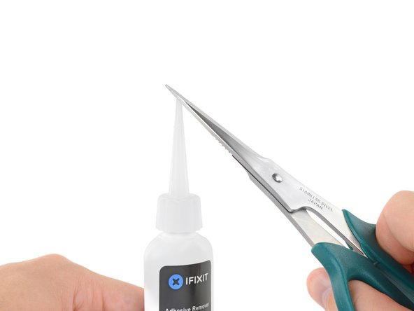
Pull off the black rubber stopper from your bottle of adhesive remover.
-
Use scissors to cut off the sealed tip of the applicator.
-
-
Este passo não foi traduzido. Ajude a traduzi-lo
-
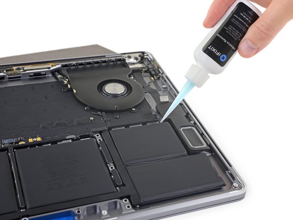
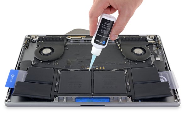
Apply a few drops of adhesive remover underneath the two battery cells on the right, starting along the edge nearest the fan.
-
-
Este passo não foi traduzido. Ajude a traduzi-lo
-
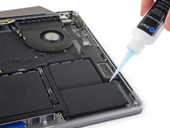
Add a few more drops of adhesive remover in between the two battery cells on the right, so that it flows down underneath the lower battery cell.
-
Wait about two minutes for the liquid adhesive remover to penetrate and weaken the battery adhesive before you proceed to the next step.
-
-
Este passo não foi traduzido. Ajude a traduzi-lo
-
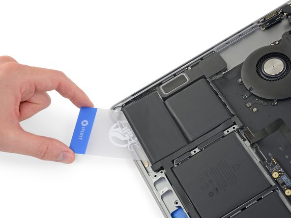
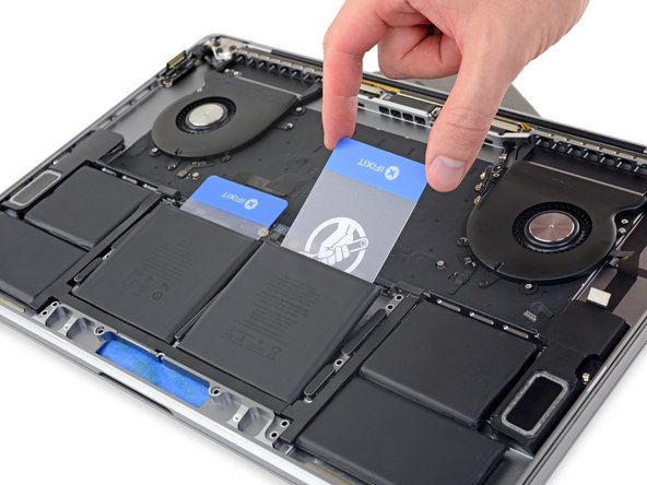
After a couple minutes, insert one corner of a plastic card underneath the battery, starting from the lower edge of the bottom, right-most cell.
-
Wiggle the card from side to side and slide it all the way underneath both battery cells.
-
Lift the cells to fully separate the adhesive, but don't try to remove them from your MacBook yet.
-
Leave the plastic card temporarily underneath the cells to prevent the adhesive from re-bonding as you proceed to the next step.
-
-
Este passo não foi traduzido. Ajude a traduzi-lo
-
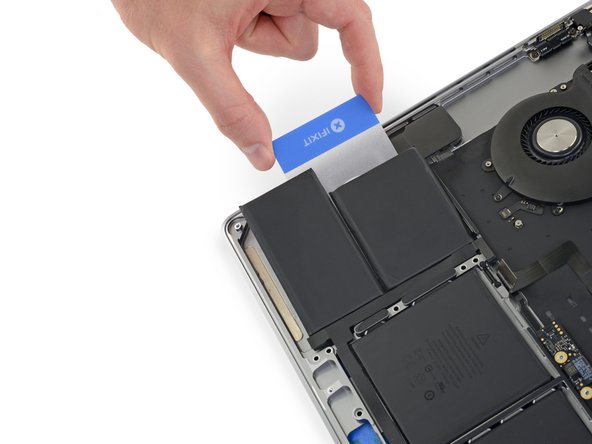
Switch to the left side of the MacBook Pro, and repeat the previous step to separate two more battery cells.
-
Leave the second plastic card in place temporarily.
-
-
Este passo não foi traduzido. Ajude a traduzi-lo
-
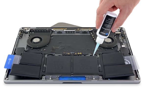
Apply a few drops of adhesive remover along the top edges of the two center battery cells.
-
Be mindful of leaks, and apply more adhesive remover along the side edges if needed.
-
-
Este passo não foi traduzido. Ajude a traduzi-lo
-
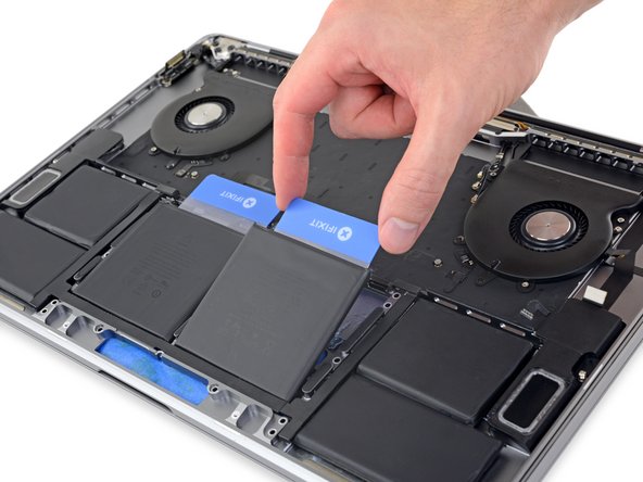
After a couple minutes, retrieve your first plastic card and insert one corner under the top edge of one of the center battery cells.
-
Wiggle it from side to side and slide it underneath the battery cell until all the adhesive separates.
-
-
Este passo não foi traduzido. Ajude a traduzi-lo
-
Retrieve your second plastic card and repeat the previous step to separate the remaining center battery cell.
-
-
Este passo não foi traduzido. Ajude a traduzi-lo
-
If you had trouble getting the card underneath any of the battery cells, try working a piece of floss or wire underneath the battery cell and pull it side-to-side in a sawing motion to separate the adhesive.
-
-
Este passo não foi traduzido. Ajude a traduzi-lo
-
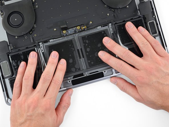
Lift and remove the battery.
-
Peel off any large strips of adhesive using tweezers or gloved fingers.
-
Scrape away any remaining chunks of adhesive with a plastic tool, and clean the underlying areas with adhesive remover or isopropyl alcohol. Wipe in one direction (not back and forth) until the chassis is clean and ready for your new battery.
-
This can take quite a bit of work, so be patient.
-
-
Este passo não foi traduzido. Ajude a traduzi-lo
-
If your battery came with adhesive pre-installed on the bottom, flip it over and carefully peel away the liner to expose the adhesive. If your battery did not come with adhesive, apply a thin double-sided adhesive tape such as Tesa 61395 to keep your battery in place.
-
Carefully position the battery and set it into place.
-
Press and hold each cell firmly for 5-10 seconds to secure it to the lower case.
-


Cancelar: não concluí este guia.
45 outras pessoas executaram este guia.


31 comentários
Amazing. This is truly thorough, and as soon as this battery starts to fail, will come back here. Nice work documenting a whole assembly line.
If I want to replace my fans, it looks like I can follow this guide to step 66 and then just figure it out from there? Is there a guide somewhere on this? Thanks!
You can do as you wrote for replacing only the fan. Ther’s nothing more to know about it.
I see that the MacBook Pro 13 logic board remains in place in iFixit battery replacement guide. Is there any reason why in the MacBook Pro 16 the logic board cannot remain in place while removing and reinstalling the battery?