Esta versão pode conter edições incorretas. Mude para o último instantâneo verificado.
O que você precisa
-
Este passo não foi traduzido. Ajude a traduzi-lo
-
With the case closed, place the Unibody top-side down on a flat surface.
-
Depress the grooved side of the access door release latch enough to grab the free end. Lift the release latch until it is vertical.
-
-
Este passo não foi traduzido. Ajude a traduzi-lo
-
The access door should now be raised enough to lift it up and out of the Unibody.
-
-
Este passo não foi traduzido. Ajude a traduzi-lo
-
Grab the translucent plastic tab and pull the battery up and out of the Unibody.
-
If the latch is depressed it will lock the battery in place.
-
-
Este passo não foi traduzido. Ajude a traduzi-lo
-
Remove the following eight screws securing the lower case to the chassis:
-
One 5.4 mm Phillips screw.
-
Three 14 mm Phillips screws.
-
Four 3.5 mm Phillips screws.
-
-
Este passo não foi traduzido. Ajude a traduzi-lo
-
Using both hands, lift and remove the lower case off the upper case.
-
-
-
Este passo não foi traduzido. Ajude a traduzi-lo
-
Disconnect the camera cable by pulling the male end straight away from its socket.
-
-
Este passo não foi traduzido. Ajude a traduzi-lo
-
Deroute the camera data cable from the channel in the optical drive.
-
-
Este passo não foi traduzido. Ajude a traduzi-lo
-
Use a spudger to pry the optical drive connector straight up off the logic board.
-
-
Este passo não foi traduzido. Ajude a traduzi-lo
-
Remove two 8 mm Phillips screws securing the camera cable bracket to the upper case.
-
Lift the camera cable bracket out from the upper case.
-
-
Este passo não foi traduzido. Ajude a traduzi-lo
-
Remove the following three Phillips screws securing the optical drive to the upper case:
-
One 3.5 mm Phillips screw.
-
Two 2.5 mm Phillips screws.
-
-
Este passo não foi traduzido. Ajude a traduzi-lo
-
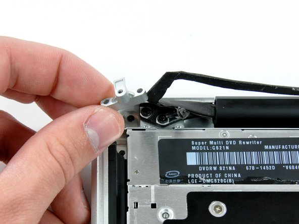
Lift the optical drive from its left edge and pull it out of the computer.
-
-
Este passo não foi traduzido. Ajude a traduzi-lo
-
Using the flat end of a spudger, pry the subwoofer connector straight up off the logic board.
-
-
Este passo não foi traduzido. Ajude a traduzi-lo
-
Remove the following four screws securing the subwoofer and right speaker to the upper case:
-
Two 3.2 mm Phillips screws.
-
One 2.6 mm Phillips screw.
-
One 5 mm Phillips screw.
-
-
Este passo não foi traduzido. Ajude a traduzi-lo
-
Lift the subwoofer and right speaker assembly out of the upper case.
-


Cancelar: não concluí este guia.
21 outras pessoas executaram este guia.
