Esta versão pode conter edições incorretas. Mude para o último instantâneo verificado.
O que você precisa
-
Este passo não foi traduzido. Ajude a traduzi-lo
-
Hold the end of the cable retainer down with one finger while you use the tip of a spudger to slightly lift the other end and rotate it away from the camera cable connector.
-
-
Este passo não foi traduzido. Ajude a traduzi-lo
-
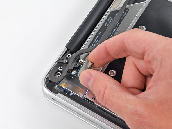
Disconnect the camera cable by pulling the male end straight away from its socket.
-
-
Este passo não foi traduzido. Ajude a traduzi-lo
-
Peel the camera cable off the adhesive securing it to the optical drive.
-
-
-
Este passo não foi traduzido. Ajude a traduzi-lo
-
Disconnect the Bluetooth cable by pulling the male end straight away from its socket.
-
Use the flat end of a spudger to pry the Bluetooth antenna cable from its socket on the board.
-
-
Este passo não foi traduzido. Ajude a traduzi-lo
-
Remove the two 8 mm Phillips screws securing the Bluetooth/camera cable retainer to the upper case.
-
Lift the Bluetooth board/cable retainer assembly out of the upper case.
-
-
Este passo não foi traduzido. Ajude a traduzi-lo
-
Use a spudger to pry the optical drive connector straight up off the logic board.
-
-
Este passo não foi traduzido. Ajude a traduzi-lo
-
Remove three 3.5 mm Phillips screws securing the optical drive to the upper case.
-
-
Este passo não foi traduzido. Ajude a traduzi-lo
-
Lift the optical drive from its left edge and pull it out of the computer.
-
-
Este passo não foi traduzido. Ajude a traduzi-lo
-
Débranchez le connecteur du câble du lecteur optique de celui-ci.
-


Cancelar: não concluí este guia.
Uma outra pessoa concluiu este guia.
