Esta tradução pode não refletir as atualizações mais recentes do guia de fontes. Ajude a atualizar a tradução ou veja guia de fontes.
Introdução
Use este guia para remover com segurança a bateria colada de seu MacBook Pro com a ajuda de um kit de reposição de bateria iFixit. O removedor de adesivos do seu kit dissolverá o adesivo que prende a bateria, permitindo que você a remova com facilidade.
Observação: Este guia mostra como se remove os alto-falantes, a placa lógica e vários outros componentes antes de proceder à remoção da bateria. Isso protege os componentes de um dano potencial pelo removedor de adesivos. Se estiver usando apenas um solvente suave como álcool isopropílico para soltar a bateria, você pode optar por deixar esses componentes e pular as etapas 6 a 45.
A Apple iniciou um recall de baterias para esse modelo em junho de 2019. Portanto, antes de substituir a bateria, você pode verificar se está qualificado para receber uma substituição gratuita da Apple.
O removedor de adesivos iFixit é altamente inflamável. Realize esse procedimento em uma área bem ventilada. Não fume nem trabalhe próximo a uma chama aberta durante esse procedimento.
Para minimizar o risco de danos, ligue o MacBook e deixe a bateria descarregar completamente antes de iniciar este procedimento. Uma bateria de íons de lítio carregada pode causar um incêndio perigoso e incontrolável, se acidentalmente perfurada. Se a bateria estiver inchada, tome precauções adicionais.
O que você precisa
-
-
Remova os seguintes parafusos pentalobe P5 que prendem a estrutura inferior ao MacBook Pro:
-
Oito de 3,1 mm
-
Dois de 2,3 mm
-
-
-
Segurando pela borda mais próxima da tampa da dobradiça, levante e remova a estrutura inferior do MacBook Pro.
If you buy the entire kit, make sure you use the opening tool! I cut both of my index fingers trying to slide it off.
Additionally, this is an “opportunity” to clean the cooling fans - and any other obvious dust magnets - with a can of compressed air. On the laptop I worked on, the cooling fans had sufficient dust to not “spin” freely - showing signs of “drag”. After blasting each cooling fan with compressed air (including from the exhaust vent side, as hitting the fins alone wasn’t adequate), they both spin freely now. No obvious signs of battery swelling on mine, but lack of adequate airflow could have been a factor with original battery aging/failure.
Good opportunity to give a good clean out. Air duster and small clean paint brush on plastic surfaces to clean up essential vents and fans. You can load fan monitor and control software to see what your your system is doing and how it improves with a clean up.
-
-
pretty hard to put it back, so I just remove the clips on the upper case....
The trick to putting it back on is to guide your fingers to the same level as the clips, and then when you put the case down move your hand from the left side of the case to the right side of the case; applying pressure when you reach the area where the clips are.
Impossible to put those peds into the upper case clips! It just does not hold there, it fits but just does the ‘click’ sound and goes back. Is it possible to buy those clips as spare part? Thank you for help.
Same for me. It just never clips, regardless of the precision and the amount of force I apply.
I also think I stripped the screws holding the clips in place. Does anyone know what screw characteristics should I look for as a replacement?
Bloated battery had already popped my clips.
-
-
Descasque a capinha adesiva que cobre o conector da bateria.
You only need to remove the tape to the edge of the flap. This is enough to be able to pry the battery connector up.
+1 to above comment
Note that the photo is taken from the hinge side - the other way to the photo in step 3
I chanced it, didnt disconnect the battery and all is well even after giving the insides a good vacuuming before changing the SSD.
You don’t actually need to remove the tape or even peel it off at all. Just pull up the battery connector up with the tape still attached.
pay attention that the macbook in this picture is presented the “wrong side”: if you accidentally remove the tape covering the trackpad cable and thereby also take the trackpad cable out of the zif-socket, your keyboard and trackpad won’t work anymore. putting the trackpad cable back into the (tiny) socket will fix the issue though.
-
-
-
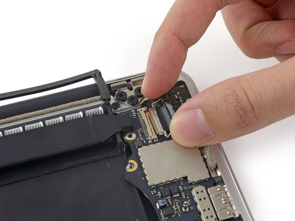
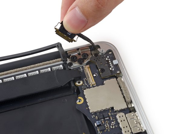
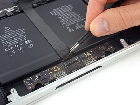
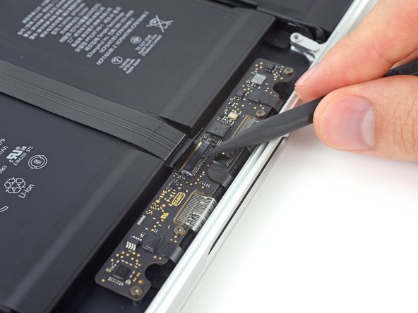
Levante cuidadosamente cada lado do conector da bateria para retirá-lo de seu soquete na placa lógica.
-
Vire o conector para trás, na direção da bateria, certificando-se de que o conector da bateria não toque acidentalmente na placa lógica.
@lawrencetaylor On any electronics repair, you need to disconnect all sources of power before you start. It’s a basic safety precaution and also removes the risk of accidentally shorting a connection somewhere (which can potentially kill your MacBook).
I chanced it, didnt disconnect the battery and all is well even after giving the insides a good vacuuming before changing the SSD.
Picture doesn’t match the computer. Hard to tell which connector to disconnect
Hi James, are you sure you have the correct guide for your machine? Try using our MacBook Identification tool.
I used the identification tool and can confirm what James is seeing. The picture doesn’t match for this step. There is no piece with visible holes punched in it.
There is an extra piece of plastic on the connector, you might want to peel that off too. It’s not in the pictures.
Ellie B -
There is a battery cover with two T5 screws that must be removed before prying on the connector.
Hi Dennis,
Thanks for bringing this up! I’ll work on verifying this and adjust the guide as needed.
I need dis board hw much
After separating the battery connector, I took the addd precaution of placing a folded post-it between the connector bank and the socket.
You can also use a plastic tool to hold back the battery connector. My connector was under the plastic tab and had no screws. You may need to check the build version as there are a number of A1398 versions.
When you install the new battery, it may look like the holes in the connector need to be slid on to the connector toward the rear of the mac. I tried bending the cable to make it work. This could damage the cables. You really need only push directly downward on the connector, as you pulled up on it to remove it initially. It will pop into place with a little pressure, just make sure it's lined up properly.
I had to use quite a lot of pressure to make the connector on my new battery pop all the way down. I thought it was down already when it was only half way, as I was afraid to use too much force. Maybe it varies between different battery brands, but just make sure that the connector should go all the way down and not have a gap between the two parts.
If you don't know what the/a logic board is, you probably shouldn't be opening devices.
Art Hackett. Not useful. This guide is for laypeople. Nobody is supposed to know much of anything. That's the point of the guide and the existence of iFixit. You could have used that time to explain what the logic board is for people who are already here anyway.
Anyway onward and upward. If you don't know what a logic board is and you're here. https://www.google.com/search?q=macbook+...
There, now you're an expert like Art. -
-
-
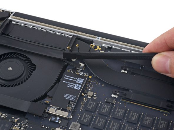
Com uma espátula ou uma pinça, levante os três cabos da antena AirPort de seus soquetes na placa do AirPort e vire-os para cima e para fora do caminho.
When reconnecting these tiny wires, use one hand to guide and align the connector by holding the wire and the other hand to press them down with a flat end of a spudger. Spent 10 minutes figuring it out and connecting the first one, then only a few seconds on both of the remaining connectors :)
If you try to do this with one hand, it’s extremely easy to move them out of the alignment while pressing them down.
I think there is a better way - where you disconnect the wifi card using the black screw in middle of wire 2 and 3 first and then untie these connectors. I pryed away the connectors but the sockets on the card were all damaged during the process. Ended up having to get a replacement card before reassembly could be completed. So again there are 2 components - connectors which are being pryed away and really fine and delicate socket. Very easy to damage them. Better to take the card off and delicately peel these connectors off. I would not recommend using these pry sticks mentioned here for that.
ATTENTION ! Cette étape est grandement sous-estimée, aucune mention de la délicatesse de l’opération contrairement à d’autres étapes bien plus facile… De plus, il semble possible de sauter cette étape en déconnectant seulement la carte comme expliquer sur la version anglophone du guide !!! J’ai endommagé le connecteur le plus proche du ventilateur, pour rien… Heureusement, tout semble fonctionner correctement…
AirPort/Camera Cables? not AirPort/Bluetooth Cables?
Agreed with Abhishek - removing the wifi card first makes this much easier.
How do you know which is which when reassembling?
I highly suggest against disconnecting these wires. It's very likely that you will damage either sockets or wires. Do as others recommend, just remove the network card. Prying tool is not good for this step. I broke 1 out of 3 sockets. I wish I read all the comments before operating. Now I gotta get another card :(
what size driver does this require? My pentalobe doesnt seem to be the right size.
As many have mentioned, don’t disconnect the wires is reallly a pain in the a… to connect them, it wont be easy and will take a lot of patience….. Better disconnect the card and carefully leave the wires connected.
Just finished replacing both speakers using this guide. VERY good. I did not remove the individual wires - just removed the card with wires attached. Seemed to be the safer, easier way to go.
How? can you explain the procedure?
I’m attempting taking the card out but leaving the wires attached as mentioned. A Torx T5 worked for me on that screw. I then very slightly lifted up the end of the card where the wires are attached and pulled it straight out of the slot on the opposite side.
Just finished replacing my display LVDS Cable with this guide and another one; awesome. I as well just removed the card and left the wires attached. Much easier.
This is one of those skills that you get experience right after you need it.
I learned these connectors doing RF work. They require a deft touch. Put slight downward pressure while you work to align the pair. Once you get the hang of it, you will know when they are aligned, and they will go back together with a light push and make a slight snap.
If they don’t immediately pop together with a light push, they’re not aligned quite right. Don’t force them, they have a very limited number of make/break cycles.
The cables should retain their bent shape well enough to show where each goes. One it too short to go too far off, and one is too long to fit to the nearest connection.
I did not bother with the danger of removing cables or cards or logic board. I spent 30 mins removing my battery carefully, using string and CT1 multisolve which isn’t dangerous to plastic.
i slid my string under the battery and see-saw underneath and sprayed Ct1 Multisolve underneath. I’ve now done both my macbooks. Didn’t destroy any cables or risk it. I put a few paper sheets over my logic board to cover any spray back. Simple see-saw and a palstic card, the blue spludger and the black long spluger.
Yes, I did the full board disassembly on my 2012 macbook last year and once I finished I kind of wondered why I didn’t just work on removing the battery. Is there any real obstacle to doing so here? Can I just spend an hour or so carefully removing the battery? What’s the risk of doing that? again, is there any actual obstacle to removing the battery without pulling out the whole board assembly?
You can go straight for the battery if you’re confident enough to improvise a little. Removing the board makes sense if you’re trying to protect the speakers from getting chewed up by the solvent. Otherwise, it’s faster and easier to leave the board in place.
Agreed. Just replaced the battery on my 15” MacBook Pro 2015 and I skipped all instruction between step 6 and 46. I just unplugged the battery and removed the trackpad connection. Used some dental floss to cut through the adhesives and a card to help with carefully prying the batteries up. After the battery was removed I used some isopropanol to clean up from the old glue. Installed new battery, attached the trackpad connection ribbon and connected battery. All in all it took me less than one hour. I would not recommend removing the whole logic board just to replace the battery.
Mackie72 -
I’m one of those unfortunate ones that simply followed the iFixit instructions before reading the comments. On successfully reconnecting 2 of the cables and (miserably) failing with the 3rd, I realized the relevance of the comments. I decided to take a gamble and leave the 3rd connector unconnected and fired up my MacBook … strangely enough, everything works fine i.e from the comments, WiFi, Bluetooth, Camera (et al) should be affected but they are all still fully operational (maybe they’ll die with time - I hope not). I don’t like the thought of an unattached cable lying around in my Mac hence I agree with those advocating for alternatives to this step (unhinging the WiFi card as opposed to prying these cables).
Diese drei winzigen Stecker wieder aufzusetzen war tatsächlich die größte Herausforderung der ganzen Reparatur! Wichtig ist dabei darauf zu achten, diese waagerecht und passgenau aufzusetzen. Ich habe dazu die Lupe meiner Lötvorrichtung genutzt und zum aufdrücken die flache Seite des Spudgers.
These antenna connectors are the worst to reconnect. Depending on the model and what repair you are doing, you may not be able to avoid disconnecting them.
We took the advice of leaving the wires attached to the card, and unhinging the wifi the card cable. Worked great for us.
Ditto on just removing the card and leaving the antenna connected. Worked fabulously.
If you do need to get the cables back on the the card, I have found good results using the tip of a T5 driver to gently push them down (of course while aligning carefully with other finger). It gives a firm, flat & precise surface to press with + we know you have a T5 around!
Why do these wires/sockets need to be removed at all? They seem like they are pretty faraway from the battery.
As we are only replacing the battery, you can safely skip steps 6-26 and 28-48, no need to disassemble the computer to pull out the battery. Use nail polisher remover I was able to pull a super bloated battery out, without disassembling my MacBook.
If you’re just replacing the battery, after step 5 you can skip everything else except 26-27, 34, and 50, and then continue from step 56 onwards. Instead of needing an adhesive removal, I just used a credit card to separate the battery cells from the casing they’re glued to.
After step 5, I would skip 26-27, 34 and just to 46-50. You need to remove the cable from the battery, so even if you do 26-27 and 34, you'll need to do 46-50.
I use the solvent to remove the left over glue after the battery has been removed, but have been able to separate the battery by just sliding a card between the battery and case.
I'm here to tell you that it is possible to remove and reassemble these wires, despite all the above comments making it seem almost impossible. I was planning to remove the entire card instead, but accidentally popped one of the wires when trying to get the card out. So then I just figured I might as well follow the instructions. Popping them was easy, getting them back on was a bit more tricky. Use a fine tip plier to hold the wire and place the plug in place, then press down (quite firmly!) with a spudge or something flat (I would advise against using a metal tool such as the torx driver, in case you slip and hit something). As long as the plug is directly above the connector and aligned properly, you won't break it. Use a good light source and a magnifying glass if needed. I brought my adjustable desk up to eye level so I could come really close and see what I was doing.
Before removing the wires, I recommend marking each with for example some tape so that you know in which socket to place them when reconnecting them later.
I got to this step and read a few more and was like oh shoot. I cannot be without my laptop if i mess something up and break a cable. The advice was right. I skipped all the extra removal pieces and just removed the battery. I did step 1-5. Then did step 26 and 27. Then steps 33 and 34. The finished with steps 46-51. I didn't have the blocks so i bypassed putting the laptop on a slant. so after step 51 i skipped to 56 and just started prying off the battery with a credit card and other ifix it tools. I do think the adhesive remover would be very helpful. I also wore goggles cause i caused a spark when i accident poked one of the batteries. Laptop is fine but it is very time consuming and difficult. I recommend getting the kit with the battery. Its only 10 bucks more and i think it would have saved me heaps of time!!!
Just don't do it! Like is says at the beginning, if you use a mild solvent like isopropyl alcohol, you can skip steps 6 - 45. My battery was pretty swollen and had already partially detached itself, so a little alcohol and some working with the plastic cards was all it took to get the battery freed up. Saved a lot of risky work!
This video shows how to remove the battery without all the steps explained here https://www.youtube.com/watch?v=JZ_jB9fR...
If you are careful, you can completely skip steps 6-25 and 28-45 and remove the battery pretty easily; I have done this battery replacement several times and did not have to disassemble the entire MacBook to do so.
Holy cow I removed the battery using the linked video’s technique and some patience. The batter is stuck to the chassis with double-sided tape. With care the battery can be removed without dissolving the adhesive or removing all of the parts. It seems to me that the risks of carefully removing the battery from the tape are lower than removing all of the components as presented in these instructions.
Take the Wifi-card out instead! It's just one screw.
-
-
-
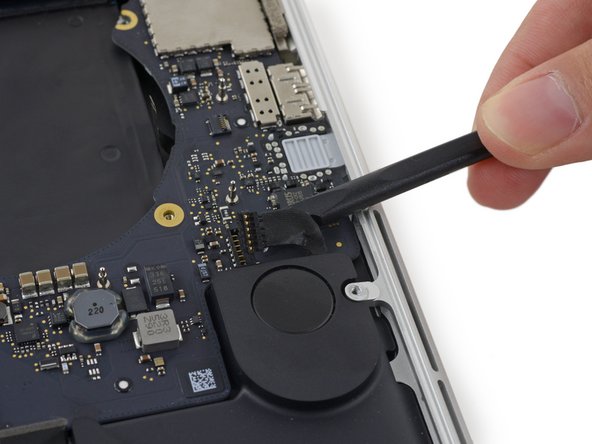
Com a ponta pontiaguda de uma espátula, empurre o conector do cabo da câmera para fora do soquete na placa lógica.
This connector is very fragile, the left edge of mine cracked off and ended up in the socket. And during figuring that out the cable or the socket appears to have got damaged because “no camera detected”.
Yeah, same here.. Not sure what to do now
Have you found a solution to this problem ? I have the same issue
All connectors are incredibly fragile. I damaged the fan connector locking latch just by trying to lock it back in place. Fortunately the cable, by the way it inserts, it’s being pushed in rather than pulled on, however, I do have concerns with it not making a proper connection. Malcolm, I am wondering how you fixed your damaged connector?
The connector slides into the socket so using the flat end of the Splunger under the cable and gently lifting draws the connector apart.
Don’t use the flat edge of the spudger. Instead, use the pointed end to gently slide off by the dog ears of the plug. If you look closely you’ll see a notch on each side.
supplied tool does not have a fine enough point here - won’t move at all
I used the fine point and also used the tweezers under the plug to relieve some pressure. I was very, very careful and made small moves. I seemed to get it out with no damage.
Thanks for your comments guys! The ones about the twiners were a BINGO! :-)
-
-
-
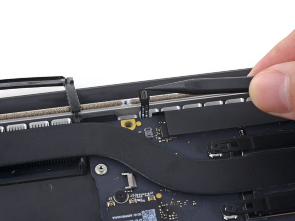
Com os dedos, puxe os cabos do AirPort/Câmera para fora da ventoinha.
-
Desprenda cuidadosamente os cabos da guia plástica de cabos.
Leave them attached. Remove the single screw holding the board in place and gently wiggle the airport card out (see Airport card removal instructions). Fold the card up and towards the rear of the computer. Now follow the instructions for the camera cable removal. Lift the airport card with the three leads attached and the camera cable up and fold the, to the outside of the case.
This video shows how to do it safely: https://www.youtube.com/watch?v=AabLlHT5...
Undo the 3 cables gently. remove the airport card. gently pry away the cables fro the fan plastic. then the camera cable will slide out easily.
I was afraid to just pull on any cables adhered, so I used a spudger edge to very gently “scrape” them up instead.
It was much easier following the instructions on the YouTube video, thanks! Looks like the process starts around 4:11.
why are we completely tearing the computer, just to replace the battery?
surely tearing it down could do more damage than being careful removing the bloated battery
-
-
-
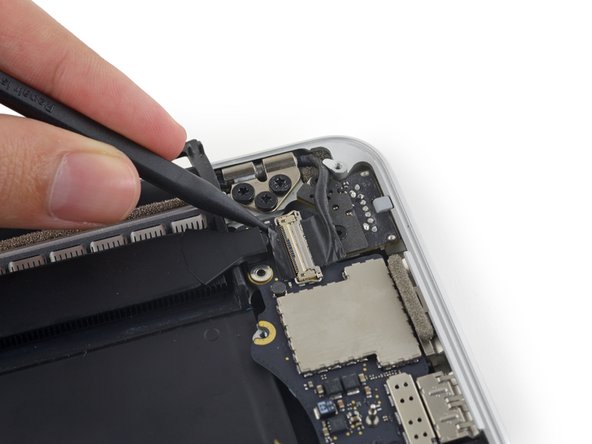
Remova os quatro parafusos Torx T5 de 2,2 mm que fixam as capinhas dos conectores do cabo da placa de E/S.
why is this needed for upper assembly replacement?
My cable connector covers are not screwed down. Mid 2015 15” MBP. That’s the computer in the title of this article so idk.
I’m having trouble breaking the 2.2 mm screws loose and I don’t want to strip the head. I’m using the T5 screwdriver. Does anyone know any tricks or suggestions?
Ok, so the correct size Torx is the T4, not T5
Is this really necessary just to replace the LEFT speaker?
I'm replacing the speakers and one of these 4 screws is longer than the others. unclear of it's size so it helps to pay attention to the size/what they look like when taking them out!!
-
-
-
Remova a capa do conector à direita.
-
Com a ponta plana de uma espátula, erga a extremidade direita do cabo da placa de E/S de seu soquete na placa lógica.
When re-assembling, the right connector cover is the smaller of the two.
-
-
-
Use uma chave Torx T5 para remover os três parafusos a seguir que fixam a ventoinha direita à placa lógica:
-
Um parafuso de 5,0 mm com um ressalto de 2,0 mm
-
Um parafuso de 4,0 mm com uma cabeça larga
-
Um parafuso de 4,4 mm
The orange colour coded one is more mushroom shaped than the other screws (their size is not easy to otherwise tell apart)
-
-
-
Com a ponta pontiaguda de uma espátula, virar para cima a aba de retenção no soquete ZIF do cabo plano da ventoinha direita.
A note about these ZIF sockets - the retaining flap is just held in place by the small amount of friction, and on reassembly they can separate. I learned to push them down with my finger when possible, or else with a flat end, carefully walking them down side by side to keep it as even as possible. If the flap separates all is not lost ! It’s quite difficult (I did almost everything in this guide with tweezers under magnifiers) but if you remove the cable first, you can get the plastic “comb” back under the pins and up into it’s original position, then replace the cable and try again.
I was gonna comment that I broke the retaining flap off the connector, but per Matt’s comment above I guess it just separated off.
Anyways while holding the flap part in a pair of needle nose tweezers the tweezers closed and shot the flap off like a bullet somewhere in my living room lol. So be careful if it does separate on you haha.
These plugs are HORRIBLE. Make sure you only pull the ribbon. All three of my ribbons came off with the plastic clip, and they are impossible to put back on. I broke all three of these the same way. (Both fans and the mic) Everything else was pretty easy. Anyone need a door stop?
-
-
-
Levante a ventoinha e empurre-a com cuidado em direção à borda traseira do MacBook, para liberar o cabo da ventoinha do soquete.
-
Remova a ventoinha.
I recommend pushing the cable connector away with a spudger instead of using the fan to pull it away…there seems to be too much stress put on the cable using the method proposed here.
Using a spudger does help alleviate stress on the cable. I also used it to help get the cable up from being adhered to the logic board.
Adding to the other comments, the fan is very light and has no resistance lifting out of the place it sits in.
I carefully lifted the fan just before there was any tension on the cable.
With the fan held in my right hand and spudger in my left, I moved the spudger under the fan approaching from the left side.
This allowed me to easily place the flat end of the spudger under the cable where the thicker plastic sits and gently pry the cable up until the cable broke away from the body.
I then used the pointed part of the spudger to gently pry the connector part of the cable away from the socket while gently pulling the fan away until the cable was disconnected and the entire fan was free.
Terrible instructions on this one. I thought I was supposed to pull the cable off the bottom of the fan! Not photos showing the final result. Finally the cable on the right came away from the board and out of the socket with the flap lifted up. Please make this clearer or damage to the cable can take place.
Instructions are faulty. After removing fan screws and lifting the retaining flap, lift the fan with one hand while gently pushing the connector with the flat side of a spudge toward the back of the chassis. It should slide off.
I definitely needed to use the spudger to gently lift the cable from the board while holding the fan with one hand. The cable was stuck on the board pretty well. Once I broke the seal it was a simple case of pushing it out of the connector.
-
-
-
Erga a tampa de borracha esquerda da ventoinha e vire-a para fora do caminho.
-
-
-
Remova os três parafusos a seguir que fixam a ventoinha esquerda à placa lógica:
-
Um parafuso Torx T5 de 3,6 mm com cabeça larga
-
Um parafuso Torx T5 de 5,0 mm com um ressalto de 2,0 mm
-
Um parafuso Torx T5 de 4,4 mm
the yellow one may not go back in during reassembly unless the board is perfect. Stripped mine in the effort - put back together without this screw :(
I ran in a similar misalignment so had to bend the top left loop a bit to make it fit.
Not a big issue, but better to lay it in and check the alignment of all screw holes (and adapt if necessary) before putting the screws in.
I saw my replacement part had already a bit of paint missing at the top left and bottom right holes, so I assume it is a refurbished or sourced part, so a bit of tweaking may be necessary. BTW, the fan works perfectly, no more annoying clicking noises.
The red-coded one is the most mushroom-shaped screw this time. (biggest, flattest screw head)
-
-
-
Com a ponta de uma espátula, levante o mecanismo de trava do conector da placa de E/S.
-
Vire a espátula e use a extremidade plana para deslizar o cabo de E/S para fora do conector.
The locking-bail is on the the cable part of the connector.
I think it would be easier to understand if there was a picture showing how the connector slides out
-
-
-
Remova os dois parafusos Torx T5 de 3,1 mm da placa de E/S.
Remove the screw holding the heat pipe, it blocks the I/O board from coming out
It's interesting that you had to remove the heat pipe screw. This didn't seem to be in the way for me. The I/O board came out quite easily without any issues.
But… it could be different for others as it was for you. I just thought I'd share my experience.
Thanks for the tip! I also had to remove that screw to get the board out.
The board was not coming out for me until I removed that heat pipe screw. Thanks for the tip!
Also make sure the I/O cable removed on previous step is out of the way before screwing this down
Me too. The heat pipe screw overlapped the I/O board slightly, but very securely held it down on mine. Had to be removed.
-
-
-
Levante ligeiramente a borda interna da placa de E/S e puxe-a em direção ao centro do MacBook, afastando-a da lateral da estrutura.
-
Remova a placa de E/S.
You do not need to undo all the screws, just the thin strip over the battery and the battery connection to the motherboard. I used isopropyl alcohol and a metal business card to slide under the battery and worked my way from left to right. Cover the leading edge of the metal business card with isopropyl and it will be easier, it deteriorates the glue and eases the process. Took 5-7 minutes. Tried to add photos to show it was possible, but this site wouldn't let me.
-
-
-
-
Remova os dois parafusos Torx T5 de 2,2 mm que fixam a capa do conector do cabo do touchpad à placa lógica.
-
Remova a capa.
I'm confused why it's necessary to remove the entire logic board to replace the right speaker?
Don't you just need to remove the I/O board for the right speaker?
-
-
-
Remova os seis parafusos a seguir que fixam o conjunto da placa lógica à estrutura superior.
-
Um parafuso Torx T5 de 3,8 mm
-
Dois parafusos Torx T5 de 5,7 mm
-
Um parafuso Torx T5 de 5,6 mm (este é prateado e tem uma cabeça mais alta do que os outros)
-
Um parafuso Torx T5 de 2,6 mm
-
Um parafuso Torx T5 de 3,2 mm
This step is really best done after all the cables are removed (Step 40).
On the other hand, when reassembling, keep the screws until this step 29
The red screw above is the same one I had to remove to remove the I/O board back in step 24
You should really do this colorblind-proof...
-
-
-
As etapas a seguir detalharão a desconexão desses seis conectores. Certifique-se de ler cada uma das etapas, pois esses conectores vêm em estilos diferentes e se desconectam de forma diferente.
-
Cabo do microfone
-
Cabo do alto-falante esquerdo
-
Cabo de dados do teclado
-
Cabo do alto-falante direito
-
Cabo da retroiluminação do teclado
-
Cabo de dados do visor
Save this step until you get to step 40
I would wait until after step 39 to remove these screws. Once they are removed, the logic board jiggles around and makes disconnecting the various cables in 31-39 more difficult.
Agree with Daniel Christie. Wait until step 39.
-
-
-
Com a ponta pontiaguda de uma espátula, vire para cima a aba de retenção do soquete ZIF do cabo plano do microfone.
-
Puxe o cabo plano do microfone para fora de seu soquete, paralelamente à placa lógica.
This cable was pretty hard to remove at first. I had to gently wiggle it from side-to-side in the socket before it would let go.
I had the same issue. This was the hardest cable to remove imo. i was afraid i was going to tear it which as hard as i needed to pull it. I ended up leaving this cable inserted until the logic board was fully unscrewed to give me a bit more wiggle room.
-
-
-
Com a ponta plana de uma espátula, erga o conector do alto-falante esquerdo e retire-o do soquete na placa lógica.
-
Com cuidado, vire o cabo para cima e para fora da placa lógica.
this cable was stuck down, so I had to wiggle the spudger under the cable first to separate the adhesive. Then it came away easily.
Same here, the cable was stuck down pretty. Thanks Pete, your advice helped a lot.
-
-
-
Retire a capinha que cobre a parte superior do conector do cabo de dados do teclado.
I wasn’t able to re-stick my tape during reassembly, not sure if that will cause issues but I’m not sure how to fix it.
-
-
-
Com a ponta pontiaguda de uma espátula, levante a aba de retenção do soquete ZIF do cabo de dados do teclado.
-
Puxe o cabo de dados do teclado para fora de seu soquete ZIF. Certifique-se de puxá-lo paralelamente à placa lógica, e não para cima.
The retaining flap broke on me during reassembly. I was careful, but it kind of got stuck. Pay extra attention and if it doesn’t give, don’t force it.
Same thing happened to me. Didn’t really put much pressure either.
meadowsd -
Same there here.. I ended up using some tape to ensure the cable stayed seated upo nreassembly
hey its not a kick, take it easy on it. after replacing my battery my keyboard (and not Richards keyboard) and track pad are non responsive, Russell Stewart old neighbour .
The last picture doesn’t show it but my cable had blue plastic material on both top and bottom, which I had not noticed during disassembly. It slid in nicely but now not sure if it is an insulating material of some kind that should have been set aside?
I can confirm blue colour of cable tip.
The retaining flap broke off on us during reassembly also…we (husband/wife team) were very careful, but the center piece just broke out when we applied pressure. the blue material did fit under the cable socket (like a smooth blue ribbon), but without the retaining lock, was unsure it would stay in position. We pulled the tape over it and hoped all would work. Everything seems to be working fine for us.
The retaining flap broke on me as well and caused a near panic. I actually managed to fix it by careful inspection under magnifier and some trial and error with tweezers. The retaining flap itself is comb shaped - a solid edge and then combs that come out between the wires., and apparently just held in by the tiniest of detents. After trying unsuccessfully to push it back down between the wires, I surmised that the gaps in the “comb” side for the wires were sealed loop and that the wires it sat on were open ended. So I eventually ended up lining the flap up as if it were closed, and then carefully nudging it up onto the top wires, which was succesful, and then pushing it back into the open position to get the detents in place. Then to close it after reinserting the cable I walked it down bit by bit by pushing forward and *downward* on each side to help it maintain it’s ‘hinging’ effect. I think frankly you’re better off pushing larger ones like these down with your finger instead of a tool.
To close my retainer during reassembly I ended up using the side of the iFixit spudger. I pressed against the entire length of the retainer in order to apply equal pressure along the whole thing. It seemed to work well.
-
-
-
Com a ponta de uma espátula, erga o conector do alto-falante direito e retire-o do soquete na placa lógica.
-
Com cuidado, vire o cabo para cima e para fora da placa lógica.
There's not much space here to work with. I found it helpful to remove the screws holding down the battery board, which allowed it to be lifted out a bit for easier access to this connector.
I used the tweezers on this and that was very effective in popping this cable out.
-
-
-
Com a ponta de uma espátula, erga o conector da retroiluminação do teclado de seu soquete na placa lógica.
On reassembly it would be great to have some tips on how to properly locate this connector…it’s kind of fussy.
Thanks for calling this out. I took a picture of the socket after disconnecting. I can see why it might have been less obvious on reassembly.
Also on reassembly - when putting in the logic board make sure this connector is not underneath. Once you have the logic board in, double check and if needed you can slightly lift up the logic board (like to take it out) and use the spudger to scoop it out.
I found that this was actually really easy to get back on by using my finger instead of a tool, as I could just wiggle it back and forth slightly until I felt it seat. Hopefully using your fingers isn’t verboten - I was strapped in at the time and everything worked out in the end.
the picture is mirrored
The picture is not mirrored if you see the heat sink that curves to the up and left it is not mirrored.
-
-
-
Com a ponta pontiaguda de uma espátula, levante a trava do cabo de dados da tela e gire-a em direção ao lado do conector de energia MagSafe 2 do computador.
+(mit dem schwarzen Klebeband zusammen)
Verwende die Spitze eines Spudgers, um den Verschluss des Displaydatenkabels nach oben zu klappen (mit dem schwarzen Klebeband zusammen) und ihn in Richtung MagSafe 2-Powerport zu drehen.
-
-
-
Puxe o cabo de dados da tela em linha reta para fora de seu soquete na placa lógica.
-
Com cuidado, vire o cabo de dados da tela em direção à dobradiça da tela, para expor os parafusos da placa do MagSafe 2.
The wording of the instruction: “Pull the display data cable STRAIGHT OUT of its socket on the logic board” could lead to errors. It almost happened to me.
Instead you should word it: “Pull the display data cable parallel to the face of the logic board being careful to keep it straight and NOT LIFT UP on the cable”.
I realize you mention it later in the warning immediately below, however, by first saying “pull the cable straight out” leads to confusion and could lead the user to attempt to interpret “PULL STRAIGHT OUT” as “PULL UP” unsuccesfully only to later notice, maybe after breaking it, that there was a warning.
Wording it properly the first time will make the warning unnecessary.
I had the same thought as I almost proceeded without noticing the red text warning.
I especially think the second warning about not touching the contacts on the data connectors should be listed before the instructions on removing it.
I think it bears repeating just how fragile this connector is, particularly on reinsertion. The problem isn’t just technicians touching the connector end; you can damage the pins simply by inserting it slightly out of alignment, or at an angle, because the outermost pins are VERY close to the edge and are very fragile. They have the appearance of being embedded in the connector but they’re actually spring traces just lying on top of it. I managed to bend the southmost pin upwards reinserting it; luckily it flattened out again and worked, but if it had not been possible to do that it’d have been a whole new screen assembly.
I’m pretty sure I inadvertently touched the connectors. Would this cause immediate errors or obscure, difficult-to-diagnose problems later in life ? Also strongly suggest using magnification when disconnecting and reconnecting this connector and others to ensure proper alignment. As Jerome said these are some of the most fragile parts of the system.
I'm jumping on the bandwagon here and saying that yes, pull the cable out towards the right (where the MagSafe connector) and not up. I also found using the tweezers made this easier.
Big fan of the tweezers.
I can't stress this enough - again: This connector is extremely fragile. After changing the right speaker and putting everything in place my display went black. Gone. Tried with the display data connector's"out an in again" very carefully - nothing. The professional technician at the service shop I asked told me he wouldn't touch that particular connector ever again.
I mean, why the logic board disassembly? Only because the speaker's cable is placed under the logic board? Why not cutting the old cable without removing the logic board and putting the new speaker in, placing the cable on top of the logic board? To avoid the necessity of disconnecting the display data connector at all costs?
-
-
-
Remova os dois parafusos Torx T5 de 4,0 mm da placa do MagSafe 2.
I didn’t take these out - just lifted the mainboard away and set it to the back while I removed and replaced the left speaker.
on my Mid 2015 MBP the MagSafe 2 board is wired to the logic board on the underside (keyboard side) so the screws had to come out. The following photo showing the logic board coming out does not show the MagSafe 2 board, so there is clearly some variation between these models.
-
-
-
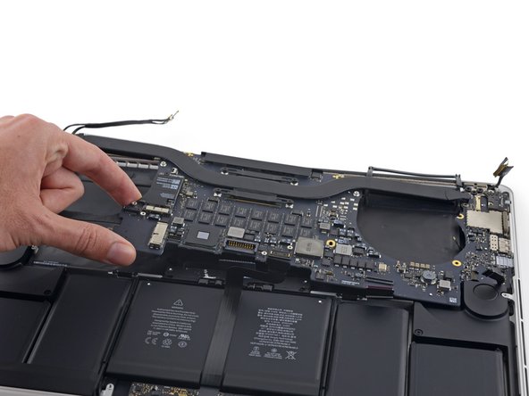
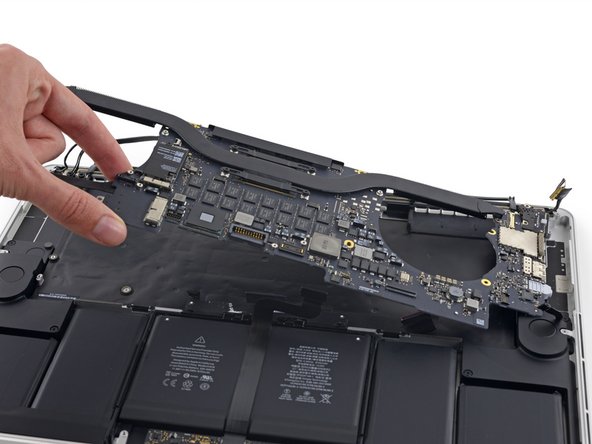
Levante e puxe todo o conjunto da placa lógica para fora da estrutura superior.
When reassembling, be careful not to leave any cables (such as keyboard backlight connector, step 36) under the board.
I had to tape most of the cables out of the way while reinstalling the logic board, because they kept returning to their plugged-in shape under the logic board as I tried to position it properly.
Also, make sure to align the right (and left) I/O properly, making sure the tabs on each port are underneath the lip of the aluminum frame. In my case, I couldn’t push the logic board far enough to align the screws until I had done this.
Yes. This step is crucial. Thanks for pointing it out!
jonvdez -
I was struggling to align it and was beginning to get frustrated. I had to look back at photos to make sure the tabs had to go under the lip of the aluminum frame. Unfortunately I read your comment after the fact. Thank you.
if you’re only removing the right speaker, no need to remove the logic board. Simply lift the edge of the logic board to remove the speaker cable.
I had to remove one of the screws from the battery board before the logic board had enough clearance to lift up.
We (husband/wife team) just slid the logic board out to right, and did not entirely remove. For reassembly, we reviewed all the cables and made sure they were positioned out of the way, or taped back, before repositioning the logic board back into position. Worth it to review before getting it back into position.
Does the logic board prevent us from removing the battery? I’m trying to figure out why we are removing it.
I agree John, tearing everything out is more of a risk then could be done ungluing the battery
Because the acetone can damage the board and connections -- in case of accident ;)
kevin -
why is the heatsink still attached?
-
-
-
Remova os parafusos a seguir que fixam o alto-falante esquerdo à estrutura superior:
-
Parafuso Torx T5 de 2,7 mm
-
Parafuso Torx T5 de 6,9 mm (com ressalto de 4,5 mm)
-
Parafuso Torx T5 de 5,6 mm
-
-
-
Remova o alto-falante esquerdo puxando-o ligeiramente para fora da lateral da estrutura superior e da lingueta de alumínio que o trava.
Look for multiple tasks to accomplish when doing a major tear down. I had a bad speaker I was putting off and then the battery bloat hit so put in both speakers to make them the same age. Changing out parts on this machine is easy enough with patience and careful adherence to the guides.
Thoroughly impressed with these guides. Also great to have the zoom photo options and comments are key to get other ideas and/or options as to what works. Thank you for great support and details!
And finally - success ! These guides are a great benefit to everyone bold enough to try it on their own. The photos, the warnings, even the screw descriptions and comments - all just incredibly helpful and well done. Thank you all for your contributions !
-
-
-
Remova os parafusos a seguir que fixam o alto-falante direito à estrutura superior:
-
Parafuso Torx T5 de 2,7 mm
-
Parafuso Torx T5 de 6,9 mm (com ressalto de 4,5 mm)
-
Parafuso Torx T5 de 5,6 mm
-
-
-
Levante o cabo do alto-falante direito para liberá-lo da estrutura superior.
Small comment on starting the reassembly, make sure to check picture on step 30 so that all connectors are exposed and not covered by logic board, I wasted some time putting the logic board back in and then having to remove it again to expose some of the connectors I missed.
I had some 2mm two sided 3M 300LSE repair tape left from a previous cell phone repair Perfect for re-affixing the speaker cable to the inside of the case.
When the instructions say "above the battery" they don't mean physically above, they mean in front of -- very important, so that the cable ends up underneath the logic board (but not the connector, the connector needs to be out of the way so that the logic board goes above the cable but underneath the connector. Hope that's clear (I had to remove the logic board to get the cable back underneath the logic board)
-
-
-
Remova o alto-falante direito puxando-o levemente para fora da lateral da estrutura superior e por baixo da lingueta de alumínio que o trava.
If you are replacing the LH speaker as well this can be done at this point using steps similar to 41 to 43
Unbelievable how much teardown is required to replace a speaker.
If you just need to expose the speaker, rather than replace it (e.g. to clean it of dust), you don't have to do steps 17-42. You can just leave the cables connected and hold it up
-
-
-
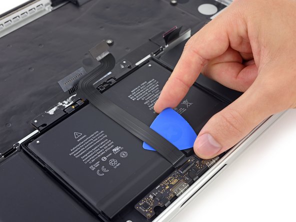
Retire a fita que cobre o cabo plano do conector do trackpad, próximo à borda frontal do MacBook Pro.
As many people noted you can pretty much skip to this step after completing 1-5, and optionally 26+27 (getting trackpad cable out the way to avoid damage)
If this is the second time you have changed the battery (I went through all the steps here to remove the first Apple original battery) you can likely skip to step 70, as the adhesive on the replacement batteries is nothing like the original. I removed the battery just by putting plastic cards under the battery cells and popping them up. I first popped the two on the right and then the two on the left, flipping them back to make room for removing the last two centre ones. Just be careful not to damage the track pad ribbon, which can get in the way if you are not careful. Saved me lots of time and no need for messing around with isopropyl alcohol.
-
-
-
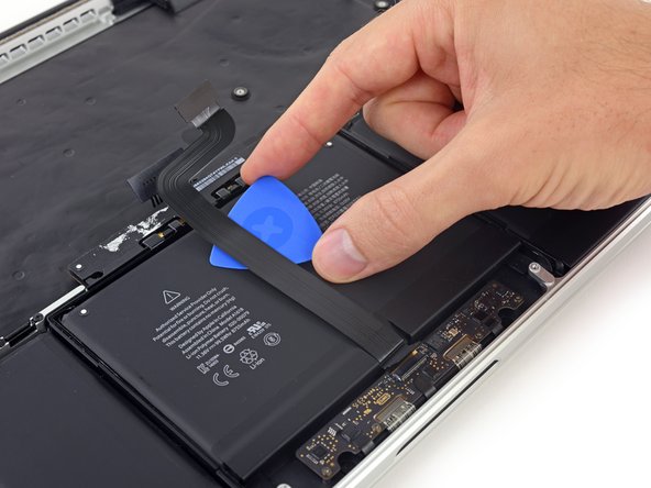
Com a ponta de uma espátula, levante a trava preta do conector ZIF do cabo plano do trackpad.
Personally I had problems getting the ZIF to disengage, so I disconnected the cable from the other side. Very easy, no problems taking the battery out and dealing with the rest of it.
-
-
-
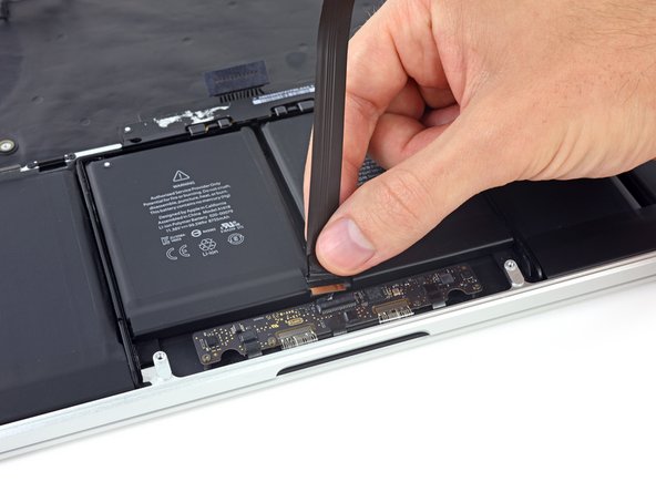
Remova o cabo plano do trackpad.
Heads up: I almost destroyed the cable, mistakenly pulling the connector upwards. In stead it needs to be pulled towards the back of the laptop body. The photos do show this, but I didn’t pay enough attention!
I goofed when re-assembling and nearly destroyed this cable. I had installed it *before* removing the plastic film from the replacement battery. Then at the end, when I realized the plastic was still there, I completely forgot the cable was on top of it and pulled it out forcibly while removing the film. Dumb. Happily, it pulled out of the locked slider without damage. But, I am posting this so others can avoid the excitement.
I had trouble with this on reassembly - the cable just wouldn't stay in the socket even after closing the locking mechanism. I thought it looked a bit weird, because I could only get the cable in very little.
After a few tries I took a closer look at the photos here and realised my stupidity - I was putting the black "pull tab" into the connector instead of the actual cable! The pull tab wasn't sticking up at an angle like in the photos here, instead it was flush against the cable, hiding the actual connector on the cable. Very stupid mistake, but very relieving to see that the cable and the connector weren't broken, which I first feared.
They don't tell you to release the locking latch. At the front side of the connector is a small black bar that runs the length of the connector. Lift that up to release the connector from the socket.
-
-
-
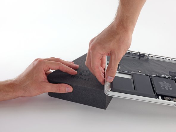
Para proteger a tela, coloque uma folha de papel-alumínio entre a tela e o teclado e deixe-a ali enquanto trabalha.
Open screen and put MacBook on it’s side
I went with Gert's idea of placing the MB on it's side. I did use a tray and paper towels to catch any excess solvent. I also found using my gloved finger as the best way to work the glue loose.
I found a easier way using tip from China battery seller. Use a 2” width plastic scraper/plastic paint scraper to poke under the battery. Use moderate strength and avoid rough handling of the battery so as not to puncture it. After 5 min of such poking, the entire battery pack can be removed without the hassle of pouring the adhesive remover from step 51 onwards. Get a scraper with a stronger handle so that it is more comfortable to poke/pry.
I thought what the !&&*, come this far so I removed the screen. Used the iFixit guide for screen removal and all prep steps had already been completed so a no-brainer to my mind, only 8 more screws and no need to worry about the acetone on the screen. looked at the iFixit guide
-
-
-
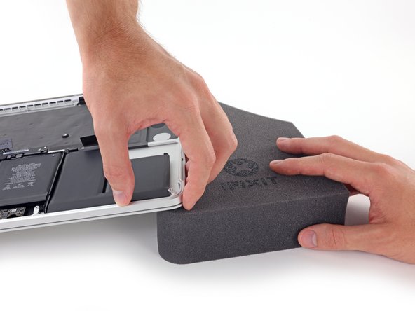
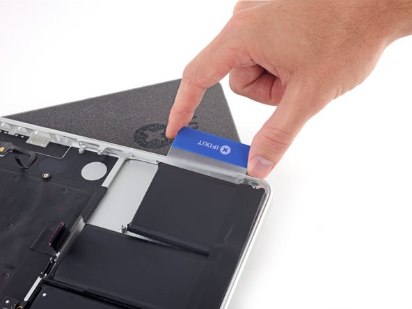
Com a borda frontal do MacBook Pro voltada para você, levante o lado direito e deixe-o apoiado ligeiramente inclinado, usando uma bucha de espuma resistente ou um livro.
This was my first battery replacement. It would have been encouraging to know that “glued in” means small lines of clue around part of the battery, actually what was once really sticky two-sided tape and not glue all over the entire surface of the battery. As it turned out, my batteries were pretty dried up and I was able to pull them out without a great deal of effort. But, I was preparing for “totally glued in” and spent a lot of time deciding if I wanted to engage in that battle.
Super helpful! I’ve been in the same boat.
Luke K -
-
-
-
Agora que seu MacBook Pro está totalmente preparado, é hora de se preparar.
-
Use protetor ocular ao manusear e aplicar o removedor de adesivos. O protetor ocular está incluso em seu kit.
-
Não use lentes de contato sem o protetor ocular.
-
Luvas de proteção também estão incluídas em seu kit. Se você se preocupa com a irritação da pele, calce as luvas agora.
-
-
-
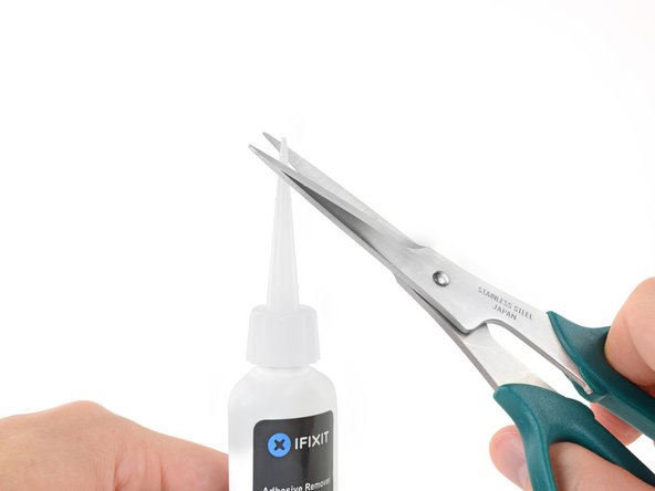
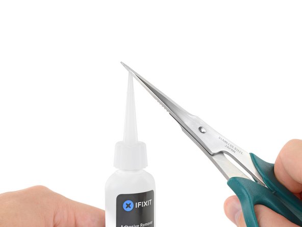
Retire a tampa de borracha preta do frasco do removedor de adesivos.
-
Com uma tesoura, corte a ponta lacrada do aplicador.
In case you’re not using the ifixit kit, this solution is almost 100% acetone. It just has some scent added to it.
You can use a bottle of acetone and a small syringe.
-
-
-
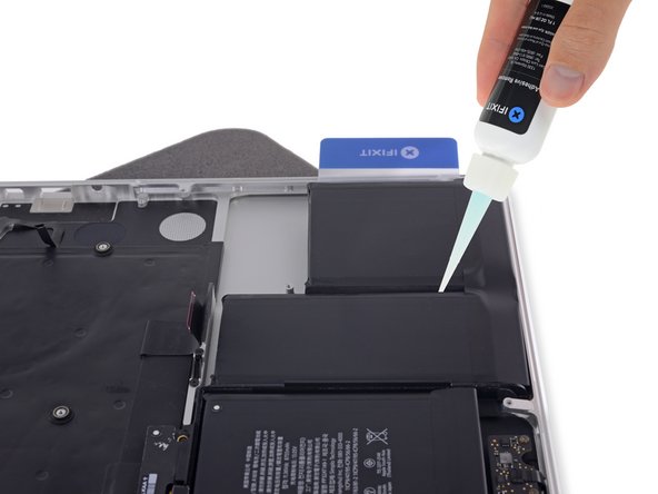
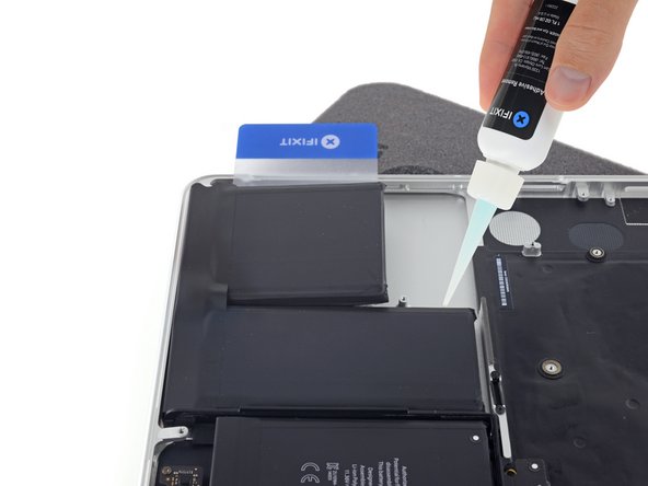
Aplique algumas gotas de removedor de adesivos uniformemente sob a borda da célula direita externa da bateria.
-
Aguarde de 2 a 3 minutos para que o removedor de adesivos líquido penetre sob a célula da bateria antes de prosseguir para o próximo passo.
The “You don't need to use very much” advice turned out to be a bit misleading. The acetone evaporates pretty quickly, especially if you are actually in a well-ventilated area. The adhesive does need a decent amount of acetone to soften enough to let go of the battery. The battery I removed had a substantial amount of adhesive, so at least 8-10 drops per battery cell was required.
It’s hard to count the number of drops being dispensed while precisely dispensing the solvent underneath the battery (so it doesn’t just splash around and on the top of the battery and evaporate), so my advice is to moisten the adhesive with plenty of solvent.
I agree with Jamie above. I had to use considerably more than a few drops but then the batteries have been in since 2015 so I would imagine that the adhesive might have become a bit harder. Also my batteries while working fine had become quite inflated and really really had to be replaced. So in inflating like small throw cushions, they also might have lifted up from the adhesive strips and they came out quite easily everything considered. I used old credit cards to keep them from becoming reattached. I also cleaned up the residual adhesive with some carefully applied GooGone and then wiped the inner surface clear with more of the iFixIt remover. It also worked to get the Goo off the little credit card tools. But I used the GooGone on my fingers. I had not touched the aeitone to my skin. Nor was I about too.
-
-
-
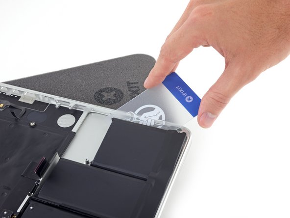
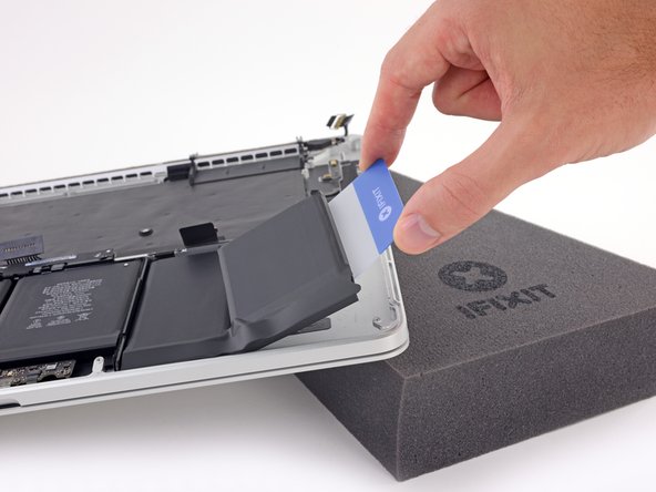
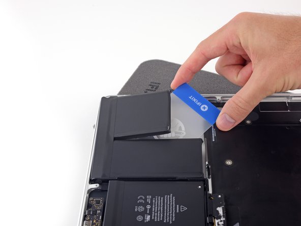
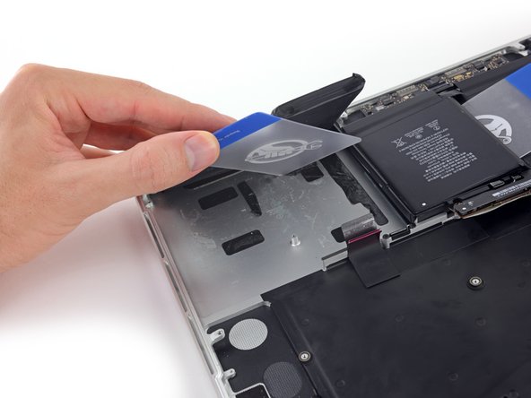
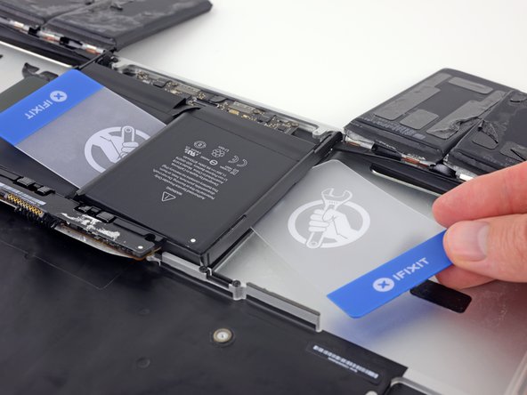
Deslize com um canto de um cartão plástico sob a borda externa da célula da bateria.
-
Deslize o cartão por debaixo da célula da bateria para separá-la do adesivo que a prende à estrutura superior do MacBook Pro.
Slide the card under a section and use it as a ramp to guide remover under the battery.
-
-
-
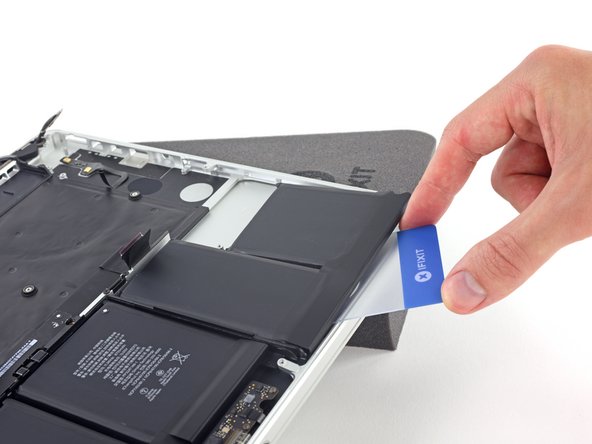
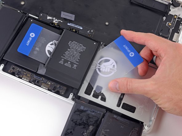
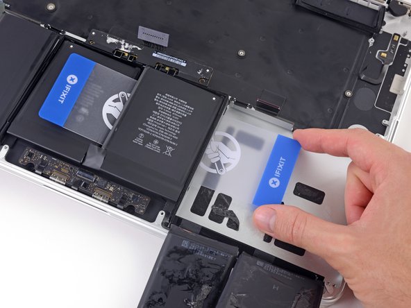
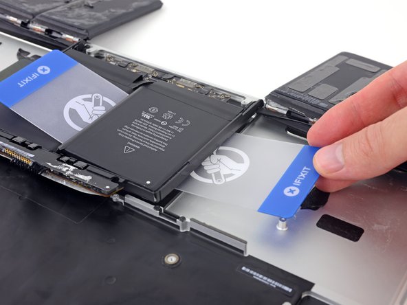
Passe o canto do cartão plástico por debaixo da segunda célula da bateria.
-
Empurre o cartão por debaixo da segunda célula da bateria e deslize-o de um lado para o outro para separar o adesivo que se encontra abaixo da célula.
-
Deixe o cartão de plástico embaixo das duas células da bateria (ou vire-as completamente) para evitar que elas se colem novamente quando você prosseguir à próxima etapa.
-
-
-
Repita o procedimento das etapas anteriores para separar as duas células da bateria deste lado:
-
Aplique o removedor de adesivos na borda elevada da célula externa esquerda da bateria e aguarde de 2 a 3 minutos para que ele penetre.
-
Coloque o canto de um cartão plástico embaixo da célula da bateria e deslize o cartão totalmente por baixo da célula da bateria para separá-la.
-
Faça o mesmo com a célula adjacente.
-
Deixe o cartão plástico descansando ou vire as células da bateria completamente para evitar que elas se colem novamente durante as etapas seguintes.
-
-
-
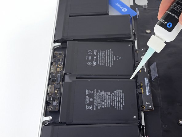
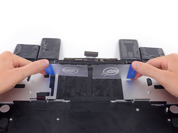
Com a borda esquerda do MacBook Pro ainda apoiada, aplique algumas gotas de removedor de adesivos na linha central entre as duas células centrais da bateria.
-
Aguarde de 2 a 3 minutos para que o removedor de adesivos penetre antes de continuar.
If you can’t get the remover to drip between the cells just gently insert one of the cards and use it to funnel the remover in.
-
-
-
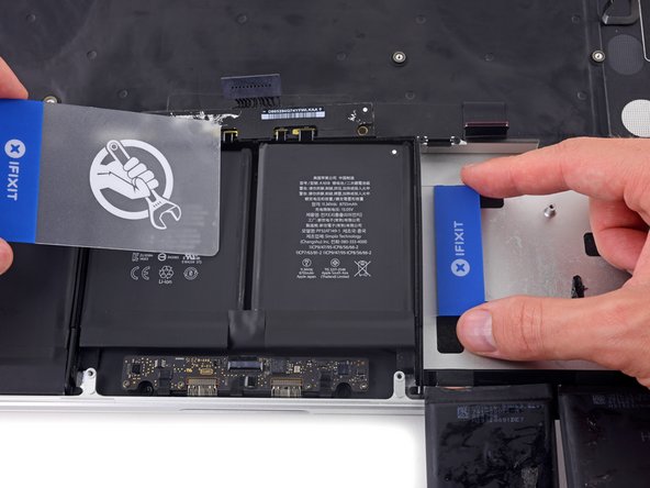
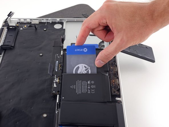
Deslize o canto de um cartão plástico entre as duas células centrais e sob a borda elevada da célula central direita da bateria.
-
Deslize o cartão mais para baixo da célula da bateria para cortar o adesivo que o prende.
-
Não tente separar totalmente essa célula da bateria ainda. Deixe o cartão plástico descansando para evitar que ela se cole novamente.
Unlike the nice flat left center cell illustrated, mine was so swollen and turgid that I couldn't get the angle to slide under the right center. I switched the order of process left to right. That is, the swollen left center battery had to be de-adhered first.
-
-
-
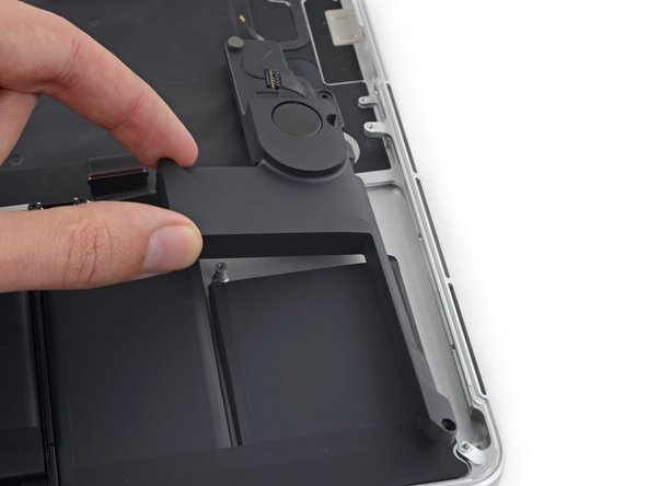
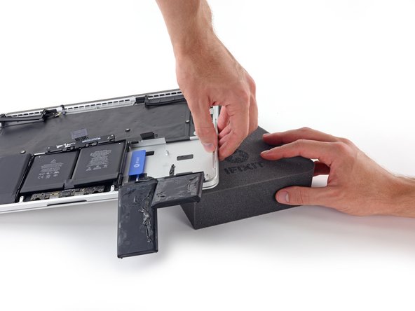
Empurre o canto de um cartão plástico por debaixo da moldura plástica da bateria e debaixo da borda ainda colada da célula central inferior.
-
Deslize o cartão por debaixo de toda a célula da bateria e deixe-o descansando para evitar que a célula da bateria se cole novamente.
Careful! The gap at the bottom is the track pad. You want to insert the card into the slot above this!
What do you mean by “the keyboard ribbon cable”? I don’t see anything under the battery, when I removed it. By the way: after the change, both my trackpad and keyboard are unresponsive. I bought a brand new flex cable for the trackpad and there was no change. Any thoughts will be highly appreciated =(
-
-
-
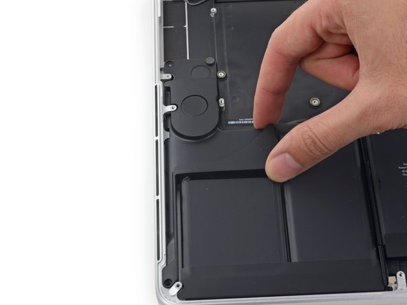
Aplique algumas gotas de removedor de adesivos entre as duas células centrais da bateria, de modo que ele escorra por debaixo da célula restante da bateria.
-
Aguarde de 2 a 3 minutos para que o removedor de adesivos penetre antes de continuar.
My battery was severely swollen, to the point where there was absolutely no space between the cells to put any adhesive remover. Instead I lifted the side of the middle cell (on the elevated side of the laptop) and put the plastic card between the battery cell and the touchpad (the black plastic thing the two middle cells are attached to). Then I held the card in like a slope and poured the adhesive remover on the card to make it run down to the adhesive, this worked great. If you just pour the adhesive remover on the aluminum body, it won't reach the adhesives of the two middle cells because the trackpad is elevated above the aluminum.
I worked my way in from the sides of both cells, sliding one corner of the card back and forth and had to use quite a lot of force for the middle cells compared to the outer ones. I suspect the adhesive bonds better to the trackpad than the aluminum.
-
-
-
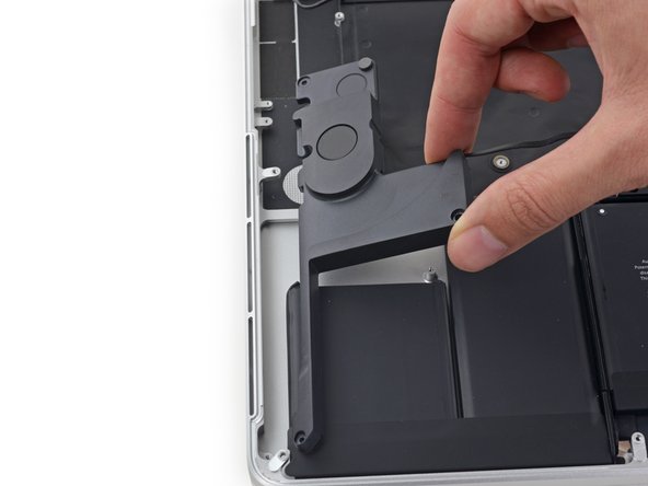
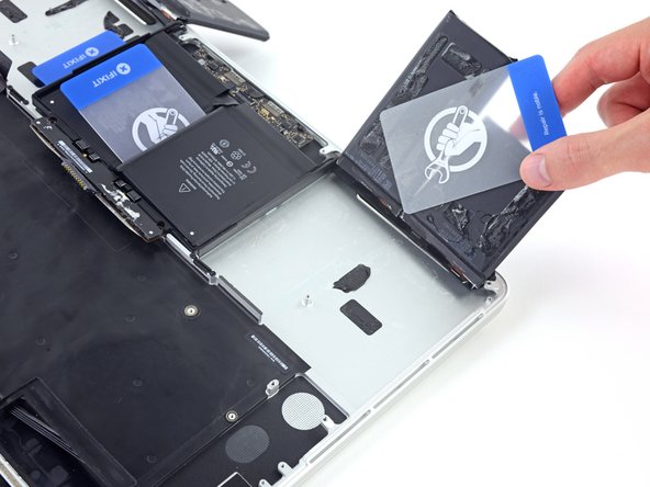
Deslize o canto de um cartão plástico sob a borda elevada da última célula da bateria.
-
Empurre o cartão mais para baixo da célula da bateria para cortar o adesivo que a está segurando.
-
Não tente ainda separar totalmente essa célula da bateria. Deixe o cartão plástico descansando para evitar que ela se cole novamente.
-
-
-
Repita o processo que você usou na célula central direita da bateria para terminar de separar o adesivo na célula central esquerda:
-
Empurre o canto de um cartão plástico por debaixo da moldura plástica da bateria e da borda ainda colada da última célula da bateria.
-
Deslize o cartão totalmente por debaixo da célula da bateria e deixe-o descansando para evitar que a célula da bateria se cole novamente.
Note: The 2 center battery cells are adhered to a thin metal cover over the trackpad. Be careful to get the adhesive dissolver under the battery and over the cover. Also, the cover is very thin and can bend. Take caution when prying to not bend or damage the cover.
-
-
-
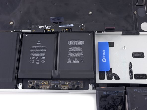
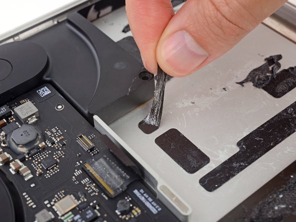
Levante e remova a bateria.
-
Com um pouco de sorte, você pode puxar lentamente cada tira de adesivo com os dedos.
-
Caso contrário, molhe cada tira de adesivo com um pouco de removedor de adesivos por 2 a 3 minutos e, em seguida, raspe-as com uma ferramenta de plástico. Isso pode exigir um pouco de trabalho, portanto seja paciente.
-
Limpe todo o resíduo do removedor de adesivos e deixe o MacBook Pro secar ao ar livre por alguns minutos.
-
Calibre a bateria instalada: carregue a 100% e deixe carregando-a por mais duas horas. Tire da tomada e use o aparelho normalmente até a bateria descarregar. Quando vir o aviso de bateria fraca, salve o trabalho e deixe o laptop ligado até ele entrar em modo espera (bateria fraca). Aguarde ao menos 5 horas e carregue o laptop ininterruptamente até 100%.
Don’t paste the new battery before complete reassembly and testing.
When positioning the new battery, pay close attention to the alignment of the two screw holes at the top.
Hear! Hear! - very important :)
Yea please make sure you line it up right. I botched this so only one was able to go in. The back panel goes back on but it does create a very tight fit since one side of the plastic cage around the two middle cells sits higher up.
I would really appreciate some additional tips on placing the new battery set. I attempted to adhere just the middle two by screwing in the battery management board, but unfortunately I dropped the batteries, and of course, they stuck immediately and needed to be pried out to be seated properly. One I got the middle two placed, I could then peel the backing for the outside four. It’s probably worth mentioning that the outside pair of batteries share space with the speaker assembly, so be careful placing those two.
I’d definitely put the speakers back before sticking the new battery down. The new battery got stuck slightly close to where the left speakers was going it, and I was just barely able to make it all fit.
Is there a reason I should adhere the new batteries? I’d opt to leave them detached, if I can. The primary concern is obviously internal movement causing premature wear on the battery cables.
I'm considering just attaching them all to a thin plastic sheet, that I tack down in a few spots. Maybe extend the sheet so the speaker screws hold it in place…
Thoughts?
You do not need too, but the adhesive is there to keep it secured to the body and not flop around and tap on the lower shell.
Ok, studied all of the comments and other videos on Youtube. Dove in last night. But I didn’t remove the logic board. I just used braided string to shimmy down each battery to separate it from the glue backing. That worked great. When putting in the new battery, I made sure that its connector was connected to the laptop, then removed the backing and placed the new battery in place. Laptop powered up, and is now charging. And keep in mind, I paid a little extra for the tools and cards and shims, they were all very helpful. If you are trying to remove a screw you don’t have a tip for, you shouldn’t be removing it. :)
the kit is actually super cool. the cards and picks were life savers!
It would’ve been helpful to include a list of instructions for replacing all of the parts instead of just making us read the instructions backwards. When I was putting the logic board back on, I didn’t realize that one of the connectors got stuck underneath the board when placing it back into the computer. After reconnecting half of the connectors I realized one of them was stuck underneath so I had to disconnect all of the ones I reconnected to lift the logic board back up and pull out the connecter that got stuck underneath. I forgot to detach the keyboard backlight connecter and when I lifted to logic board the pull out the connecter stuck underneath, I snapped the keyboard backlight cable that was still attached. Luckily this isn’t a major component and I don’t really use the keyboard backlight that much anyway, but if you included a list of instructions for reattaching everything I probably wouldn’t have had this problem.
These instructions….. Really???
I just unplugged the battery, unplugged that cable that went over the battery, and unscrewed the two screws holding the battery.
I then pried the batteries away without any chemicals and put in the new battery. Plugged in the two connectors and screwed everything back in place.
I didn’t need to completely disassemble the macbook.
I actually did he same
though I unfortunately damaged the old battery trying to do this (but luckily nothing else) - big scare!!!
- if you try this method - PLEASE DO NOT USE ANY SHARP/METAL TOOLS to try pry the battery out -
the plastic credit cards work fine if you wedge them in the corners to start gently - but firmly leveraging / shimmying your way under.
However, I was lucky, the batteries came out quite easily (don’t be afraid of the sound of tearing adhesive tape) and some people might have super stuck batteries and need to use the liquid - which then means you have to protect everything from the acetone in case it leaks onto circuitry.
Thanks Tycho, you saved me a world of anguish disassembling the whole contraption. firm, gentle and patient worked fine without liquid for me.
Good luck all you fixers !!!
Agreed. I've replaced two batteries on two different Mac Pro laptops. The first time, I did it the hard way and used the tutorial to remove much of the guts of the machine. The second time, I did exactly as Tycho did. Though, as others have noted, the old battery was swollen enough that it had begun to pull away from some of the adhesive, making the job easier. Was up and running in 15 minutes.
I have an additional suggestion on placing the new battery. With the laptop case hinge away from you, I put a piece of masking tape from the bottom (closer) right corner of the new battery pack to the bottom left corner of the battery pack with some slack in it. This allows you to pick up the bottom edge of the batteries in an arc, and position and place the center ones first. I screwed in the battery controller, pulled the heavy plastic backing off of the batteries, then placed the center batteries, followed by the outside ones. be careful to stick the tape firmly. The last thing you want is the batteries coming free and falling to the case and sticking wherever they land. Good luck. This was the most stressful step for me. While you’re reassembling, give the fans and the fins of the heat exchangers a good dust with canned air. :)
The protective film covering the adhesive is one long strip that keeps the batteries aligned. It’s kind of stiff and part of it sticks out preventing the center batteries from aligning properly, so I couldn’t really check the fit. Once I pulled off the film, the left and right batteries became difficult to manage and I ended up dropping a couple prematurely. In hindsight, I think it would have been helpful to cut the film between the cells and cut out the part that was in the way first.
This was quite easy. Follow the sequence. I took a 50cm long wide tape where I put the screws head down on in order to have them in the right sequence while assembling the machine again. Timeframe was 1.5 hours.
All in all this was a great kit. The worst part is step 6. Pulling the 3 little wires off the airport card. Honestly, I would probably just take the entire card off vs those three wires… With respect to putting the new battery in, line up the two screw holes in the battery chips with the case. I also installed the speakers first just to make sure that I’d get the placement right. Other than that, there are a lot of ribbon cables so be meticulous and take it slow. This took about 3 hours to break everything down and about half an hour to put everything back together. Good luck!
Like many others here; I did not do all the steps. I would have surely broken something else. Once I (carefully) disconnected the battery and track pad ribbon cable and carefully moved them aside, I then applied the solution to the batteries to loosen the adhesive. Put my Macbook Pro on a slant to keep the solution from running everywhere, btw. Then I used dental floss to cut thru the adhesive. Didn’t have to work at it much because my batteries had swelled to the point where they had mostly dislodged themself from the adhesive. Great kit and loved that iFixit did not skimp on the tools and accessories. What a difference a new battery makes!!! After charging it and then draining it (calibrating) it seemed like it took forever for the battery to drain. Thanks iFixit!
Ohne die tolle Reparaturanleitung hätte ich den Austausch der Akkus niemals geschafft! Herzlichen Dank für die detaillierte Anleitung! Um die Schrauben jeweils wieder in der entsprechend richtigen Stelle einzuschrauben, hatte ich diese mit der entsprechenden farblichen Markierung (entsprechend der Anleitung) auf kleinen Styroporplatten abgelegt.
Thanks to these comments I’m another who didn’t do all the disassembly or use the adhesive remover.
I did steps 1-5, 26-27 and 46-50. I sawed/jabbed away at the adhesive with the plastic cards and the spudger (be careful with anything pointy that you’re not jabbing the battery—only the adhesive when you can pull it away enough to see exactly where you’re using it). My battery was badly swollen so a lot of mine had peeled up already. It took a bit of muscling but overall it wasn’t bad and I did the whole process in an hour.
How can I find out or does anyone here know whether it is at all possible to boot/start-up the MacBook Pro 15" Retina Display Mid 2015 without a battery inside it but instead, just run it with the power adapter plugged in all the time.
I have this unit and it’s on it’s way to needing another battery replacement cuz over time, the %#*@ thing ends up swelling up! The batteries that have been in were all Apple batteries installed by Apple!
Thx in advance for any help with this ?
The answer is yes- I didn’t connect the battery properly after replacing it and the computer still booted and reported that no battery was connected.
Unnecessarily complicated?
Having followed this article through, and installed my new battery, it seems to me that it wasn’t necessary to do such a comprehensive teardown.
I was cussing Apple all the way for making the most likely to be replaced component so inaccessible, but it seems that removing the logic board, I/O board, fans and all the cables that go with them is all to free the right speaker cable. I think the batteries could be carefully pried out without removing everything else. The left speaker and its cable are easily removed, and the right speaker could be tucked out of the way without being disconnected.
I wouldn’t say the whole process was difficult, but it was tedious and my only advice would be slow and steady wins the race. I’ve torn too many ribbon cable in the past being impatient and over zealous.
This seems overly complicated to me. No real need to tear the entire machine apart. I just swapped the battery following steps
1-5, 26, 27, 41+43 (yellow and orange screws only), 46-50, 55-74
To remove the battery, I opened the MacBook to 90 degrees and turned it around (like a pitched roof). With the screws removed the bottom end of the speaker assembly can be pried up by about 10mm to wedge the plastic card under the batteries. The adhesive dissolver I’ve put at the top end of the batteries so that it was running down behind, away from the speakers and the main circuit board.
As we are only replacing the battery, you can safely skip steps 6-26 and 28-48, no need to disassemble the computer to pull out the battery. Use nail polisher remover I was able to pull a super bloated battery out, without disassembling my MacBook.
Thanks for this great tuto, The battery was very well stuck… but the tool box purchased on this site was very helpful.
100% of success
A question: i replaced the battery and all works well, but a black back patch of metal sheet got connected to the old battery and i only noticed it after assembling and turning on the mac; is this metal sheet “really” important or can i go without it? I rather not go back in and redo all the work.
Does anyone have the experience of getting all the way through this (seemingly successfully) only to find that your computer doesn’t register the battery having been installed? Unclear if the battery could be a dud or if the battery connector/cable has an issue?
I just pried the battery out with an old credit card. If you go at it carefully, that's totally feasible.
I'll have to disassemble most of the machine anyways though, since i also have to replace the speakers. No real time saved :/
What if you replaced the battery and it works but now the keyboard trackpad don’t? I rechecked all the connections.
I followed the whole process, recalibrated the ifixit battery and reset the SMC, however the computer runs slow, the fans are throttled and I have experienced dramatic performance degradation. I have macOS 10.15.7.
Any solution?
I did this in 8 steps instead of 74. You can watch youtube on how to remove it without taking the macbook apart. You really only need remove 4 screws which is the trackpad connector & the screws on the battery. Just be careful & obviously don't use anything sharp or metal & you will be fine. The battery actually came up pretty easily for me because there wasn't much adhesive, it only took like 2 minutes to come up. I didn't use adhesive or the cards just the flat part of the spludger thats all I needed personally! If you need to be more aggressive with yours use the cards & adhesive.
What took me the longest was lining up the new battery to the screws & the connector. Do not remove the bottom adhesive until you line it up correctly, it was a pain & I had to keep removing the sticky battery & placing it over 15 times.
Sure wish i had read the comment first and just pulled the battery. Now i have a pooched computer with no trackpad and no speakers. Dont follow this tech!
Adhesive is such a pain. With the new battery, I didn't remove the tape that cover the adhesive and just install as it is.
Do you think that would be okay?
Also once boot up the Mac, for some reason my original password no longer work. I have to go through the Apple Id recovery option to reset the Mac login password. Seem a bit odd but it works.
The way I fit the battery into place worked like a dream.
My battery came with a thin blue "perspex" like sheet about 1 mm thick covering the adhesive. I peeled this away and re stuck it lightly across all 6 cells, but only covering half way across, leaving half the adhesive exposed towards the 2 battery screw holes.
This left enough "perspex" for me to hold onto. I held the battery at a very shallow angle, lined up to the 2 screw holes and fixed the 2 screws into place. I then peeled away the "perspex" downwards while holding the outer edge of the battery cells. Be sure to hold at a very shallow angle, there isn't much "bend" between battery and the 2 holes strip.
I then lowered the cells into place and pressed them down well.
I too did this "dry" using steps 1-5, 26 & 27 then 46-50. I found using a hair drier to gently warm the case under the outer cells helped to free them.
I found opening the laptop to 90 deg, then positioning it with the screen pointing down over the edge of a table best.
Thanks iFixit.
This was excellent advice! I screwed in the screws first, having readjusted the position of the blue plastic like you said, and then pulled it off and it was set right in place. Thank you!
heyaly -
-


Para montar novamente o seu dispositivo, siga estas instruções na ordem inversa.
Para montar novamente o seu dispositivo, siga estas instruções na ordem inversa.
Cancelar: não concluí este guia.
562 outras pessoas executaram este guia.
Um agradecimento especial a esses tradutores:
96%

Udo Baingo está nos ajudando a consertar o mundo! Quer contribuir?
Comece a traduzir ›


218 comentários
Do I need to remove all these things just to replace the battery or can I just remove the connectors above the battery than the battery?
I just went through this process yesterday, and today wondered why I needed to take all that crap out, because I don’t remember anything blocking the battery removal, that would require removing the speakers, logic board, etc. I think it’s because of the acetone adhesive solvent. It’s powerful stuff that can easily damage the system. Maybe, if you are able to get the battery out without the solvent, you can skip all the other stuff. I will say, however, that in my system, it seemed like the adhesive is real solid. It felt like I was pressing the card up against aluminum studs in the frame, until the solvent loosened it up. If you try to remove the battery without the solvent, be very careful not to use excessive force and warp your frame.
See the post I just added, it seems that this is all to be able to remove one of the speaker cables, which I don’t think in necessary. I really don’t like messing with delicate connectors and ribbon cables that I don’t have to.
I have done this job before. I remember that it was easy - did it on the kitchen bar.
In hindsight, I didn't have to take out all the crap. I must have used a different guide. Son of a gun, wasted time. I easily got the battery out without "adhesive remover". Hilarious if "adhesive remover" is acetone, a chemical availabe just about anywhere. Note to self, iFixit needs to be second opinioned. I think this guide is written to make it seem like you need a lot of special tools to do this job. Not true - just a few drivers, usually provided with any battery.
I thought this too and didn't wanna do all that work with the solvent. All I removed was the battery connector and the trackpad cable before attempting to remove the battery. The adhesive Apple uses is bewilderingly strong. I thought I could pry it off with a strong paperclip and a screwdriver but it bent both. I ended up using the backend of a hammer and that worked surprisingly well. But it was super janky and I ended up puncturing the battery outer plastic. It didn't catch fire or anything but you can definitly smell the battery juices or whatever so i opened up my window. If you somewhat know what you're doing and accept the risk of setting fire to your house you can get away with not using solvent but I highly recommend doing so as the battery I ended up pulling out of my MacBook is all mangled. And if you use the solvent you have to take everything out. Apple will be Apple.
I made it within 1 hour doing Steps 1-5, then Steps 46-50.
I removed battery heating the aluminium frame in the location of battery pack on the opposite side of the frame with NTE HG-300D Mini Heat Gun, and then gently peeling this battery pack with plastic spudger. You may need to reheat the area several times.
For 2 central battery elements you can't heat aluminium frame because they are below touchpad, so I peeled batteries a little bit with spudger, heated the underneath gently, and then peeled it again. Also dental floss could help cutting the glue underneath the battery.
Thanks for your fast approach, worked fine for me as well! I did not use any glue dissolver at all.
Same for me, about an hour. I didn’t use a heat gun, just finagled the tip of the adhesive dissolver around the edges and otherwise followed the directions using the plastic cards. That dissolver is great stuff, worked twice as fast as the instructions.
Thanks for posting your short version. I did mine in about an hour with dental floss and the plastic cards. No heat. No solvent.
So glad I read the comments before going down the path of insanity.
I followed your comment to skip most of the steps and just remove the keyboard cable and the batteries. The replacement of batteries revived my water damaged MacBook Pro which stucked in boot loop.
In the beginning I tried to avoid “finagled“ situation thus only dripped a drop or 2 of dissolver each time. I also use a thin tip to induct the dissolver into the gap. But it’s very hard to do the flossing work and very slow. For the last 2 central pieces I had to drip 10 or more drops for each line of tapes which eventually helped me to remove them.
For someone who can’t order ifixit dissolver, I got my “Arctic Thermal Material Remover” from canadacomputers.com. It may not be perfect but helps. I didn’t use heat gun.
Great article, thanks!
Yan -
Did the same yesterday; took me closer to 4-5 hours as I was being “exceedingly careful”, as it was my wife’s laptop and she’d been hit with a “perfect storm”: battery died and backup was corrupt (backups.db reported a size of 0, and Migration Assistant hung while trying to look for it). o_O Otherwise, everything worked well, laptop is operational again, and my wife’s files have been backed up, migrated to another laptop, and the backed up again - so she currently has 4x copies of all her files. \o/
Zathras -
I’d recommend to do steps 26 and 27 and remove both ends of the touch pad cable!
If you are careful and tilt the whole Powerbook a bit downwards the solvent doesn’t pose any risk as it will run away from the speakers tec..
Did it nearly the same way (without heating). I also loosened the two accessible screws of the two speakers and bent them up a bit to avoid contact with the spreading dissolver and to better slide the plastic cards under the batteries. You just have to make sure that nothing splashes onto the other components when you tilt the dissolver bottle. If you are anxious, you can also protect them with a non-conductive, acetone-resistant cover.
Martin -
After reading through all of the steps, and seeing this comment, I opted to try this approach. Now, my laptop is getting quite old, so I suspect the adhesive has lost some of its original vigor. I did not need to use heat, dental floss, or the adhesive remover and was able to follow the instructions using the plastic cards to remove the battery without any damage to the laptop.
I followed the same steps and used fishing line to "rip" the glue between the battery and case. Found a video that showed it on youtube. It worked great!
Had to have a friend hold the computer in place for one "battery block" to "cut" it, but other than that, it was quite easy. :)
ssssaaaa -
>>I made it within 1 hour doing Steps 1-5, then Steps 46-50.
I also used that method - I very carefully used the minimum amount of solvent to incrementally loosen the battery for removal.
I was concerned about using heat since the old battery was pretty badly swollen - I used the solvent instead.
CCC -
Just finished this repair, I also did not remove all the components. I have never used a heat gun before, but I had a hair dryer lying around and that did the trick. I used the hair dryer even on the middle two cells and it seemed to come loose with the plastic card tools just fine.
The dental floss suggestion is interesting. I did this (1-5, 26-27, 46-50) using IPA. Using the plastic cards from the kit, the side cells came out pretty easy, but the central cells took a while. Doing 26&27 was probably not necessary
These batteries appear to be actual Apple batteries. How did iFixit remove them from the case? If iFixit didn't, were they able to get replacement batteries directly from Apple (since the adhesive is already installed)?
No idea, but check About This Mac… > System Report > Power; on the one I just replaced, Manufacturer reads “ifixit”.
Zathras -
Battery seems to be working fine but trackpad and keyboard no longer work. They were working fine before I changed the battery. I checked the trackkpad cable but that seems fine and inserted properly. Reset SMC but still not working.
Might want to disconnect and reconnect both cables (in the case of the trackpad cable, do this at both ends). Compare with the photos to make sure they're inserted far enough. Check carefully for any sign of physical damage to the cables, connectors, or the board itself. If you continue to have trouble, consider taking your question over to the Answers forum for more suggestions. Good luck!
Thanks Jeff! I'm afraid this repair is a wash. Trackpad won't even click. I will ask around.
Jeff, thanks so much for this guide. I was able to resurrect a Mid-2015 MBP that was thrown away due to water damage! It was stuck in an automatic boot loop whenever AC power was connected and would not even power on via the battery alone.
I admit that I did not do a complete teardown nor did I use the kit with the adhesive remover. I was able to lever the outer battery sections up enough with a plastic spudger to slide an old, used gift card underneath them to forcefully cut through the adhesive.
Here’s the System Information output for the installed battery part:
Battery Information:
Model Information:
Serial Number: <redacted>
Manufacturer: DP
Device Name: bq20z451
Pack Lot Code: 0
PCB Lot Code: 0
Firmware Version: 702
Hardware Revision: 1
Cell Revision: 3241
Charge Information:
Charge Remaining (mAh): 8635
Fully Charged: No
Charging: Yes
Full Charge Capacity (mAh): 8723
Health Information:
Cycle Count: 1
Condition: Normal
Battery Installed: Yes
Amperage (mA): 900
Voltage (mV): 13029
Great job Jeff. Didn’t seem like there was a need to remove everything, but I’m glad I did. It’s all clean and working perfectly again. Best of all, no bulging battery warping the case!
Just did this today, January 17, 2018. Took me about 3 hours. The instructions were awesome. Taking the battery out was actually far easier than I imagined it would be. Really appreciate you guys making this guide. Apple was going to charge me $1500 to replace my battery, but I did it myself for $120.
I recommend people to check out the thread trick soo you dont need to remove all the components inside! You basicllyy just need to take of the backplate. remove two screws on the battery frame and then use a thread to cut the gluestrips between battery and bessel. I used builder string for leveling as its strong and thin. I used roughly 5 min to remove the battery from the bessel, and then another 30min to clean of the old glue. I recommend the Arctic Thermal removal (mainly for cleaning cpu), it resolves the glue at makes it gel like, then use a spachelor like the one you get un screen replacement kit and scrape it of, use a cloth or toilet paper to remove the liquid undderway. Since its in such a small bottle with drop adding you do not risk damaging the screen etc due to the acid. One of my most easiest repairs i have done! ifixit should update their approach with an alternative. Youtube “macbook retina battery replacement“ ;)
I agree with everyone that you don’t need to go through the entire process. Do Steps 1-5, then 46-50. WARNING: use as little force as possible when removing the battery, as you most certainly will rip or disconnect something else if you are not careful. Take special care with the keyboard/trackpad ribbon. When I did this repair I somehow ruined the keyboard/trackpad ribbon, and neither worked until I put another ribbon in—which is very easy. They cost pennies to replace, so you might even want to have some on hand. Everything works perfectly now!
I just did the swap, followed all the directions (and it did make sense to me to do it properly and remove the speakers and everything to avoid damaging anything) . Either way, when I booted back up and am doing the initial discharge, my battery indicator has turned red and says “service battery” I am not sure if this is just because its in the middle of calibration, or if there is a problem. I assume there is no problem, but worth mentioning that it showed up.
Did a full calibration cycle (that took for EVER because this battery (thankfully) lasts so much longer than my old tired one!!! woohoo!) All is well. If you get the red battery light just complete a full calibration cycle and bob’s your uncle!
Heh… I ended up opening up the most CPU intensive programs I could muster to drain the battery for calibration. It definitely did last longer that I was anticipating. Yay for a fresh battery!
Worked for me too—I followed all the steps before I read the comment thread here. Wasn’t that big a deal, although I can’t say I was confident that everything was going to work when I switched it on, but all is good. Great instructions—thanks!
my mac won’t start after the replacement. booting in “scan for new hardware” mode, says that the new installed battery is faulty…
Being as cheap as I am, I bought the battery from Ebay. Tried to be lazy and just pop the battery out of the computer. Opened the case. . .Well it actually flew open as one of the original cells were swollen. Tried to pry the battery out with freeze spray, hoping to freeze the crappy adhesive and hoping it will just pop out. Spark. . .Hiss. . .Smoke. Long story short, I ended up buying iFixit’s Adhesive remover kit. Amazing product. The included cards just cut through that crappy adhesive like butter. Also, I did the repair the long way and took everything out. Best to be safe than sorry as there is a risk in damaging the sensitive logic board with the adhesive remover or with your tools trying to free the crappy batteries from the crappy adhesive. Right now I’m calibrating the battery. Wish I bought the battery from iFixit in the first place to support such a great company with great products. Kudos!
Went slow and steady. Followed all the steps. Seem to have pulled it off. Everything appears to be working. Amazing guide and great price on the battery. Thank you.
Why did Apple make this so difficult?
Worked well, but the screen’s black. I tried resetting the SMC, zapping PRAM, and removed/replaced the display connector, but I’ve still got the same problem. FWIW, an external Thunderbolt/MiniDisplay Port screen works w/o an issue.
Anyone have any ideas?
@amowrey Just a guess, but you might want to check the display cable in steps 37-38. Make sure the socket is clean and the cable is fully inserted and locked in place.
I have the exact same issue. HDMI port working computer is otherwise functional. Backlight works on display but the screen is black. Did you ever figure yours out?
Dan -
Did This Repair using some waterproof pvc playing cards, a syringe squeeze bottle with 99.9% isopropyl and a black stick. Took about 15 minutes to free the battery, just watch out for the flex cables on the trackpad and its no problem. No real need to gut the entire frame. Would of been a bit easier with some heat applied to the outter most cells.
Replaced my battery today, everything works perfectly. Went through steps 1-5 and then 46-50. There is literally no need to disassemble the entire laptop. Thanks for this repair kit :)
By starting at 45, didn’t you meet problems with the two speakers standing in the way? They limit a lot the space in which you can pour the liquid to soften the glue, and are in the way when inserting tools to lift the outer batteries. I’d really like to follow the same procedure and avoid disassembling everything, but I am wondering if I am able to. Maybe is possible to remove partially the speakers? Their cables run under the motherboard so I guess they can’t be taken out without a full disassembly, but maybe they can just be lifted a little? Thanks for any suggestion.
I replaced my battery after being inspired by the instructions on the process. My MacBook is out of warranty and I suspected Apple would charge me several hundred dollars to fix it and require my laptop for at least a couple days. I didn’t like that proposition and decided to brave the DIY repair.
.
I bought the kit from IFixIt and received it about a week later. I’ve seen the comments about only doing the first five and last five steps. My experience with these types of things is that it’s usually best to clear as much out of the way as possible in case something goes wrong. Fortunately, little went wrong for me by following the instructions provided (well written and sufficiently descriptive).
.
I took my time and made sure I was patient when pulling cables as many of them have seemingly fragile locking mechanisms. Very much appreciate the author’s attention to detail and willingness to produce such a helpful work. As an homage to the DIY process, I made a time lapse of my effort (https://youtu.be/l4J6SFOrCQI).
Replaced a battery today, guide was very helpful and the repair went perfectly.
My Mac had a swollen battery, to the point where the chassis was bent outward both ways and the laptop wasn’t closing properly. Didn’t notice this early on since it serves as a desktop machine for me and I’m using external displays, mouse and keyboard. There are no Apple service centers in my area, so my only option was to do it myself.
There’s probably no real need to completely disassemble it (acetone, when it reacts with an adhesive used in a mac, turns into a jelly-like substance with no actual risk of flooding the internal components), but I did this anyway just to clean out all the dust inside. Now my mac is as flat, as cold and as silent as new. :)
Thanks for a great guide and kit!
I ordered the battery replacement not really knowing how difficult a surgery it was going to be. I’ve always repaired my old laptops, but never needed to do anything super major like removing the logic board. After the kit arrived, I began to review the replacement guide and was suddenly feeling really overwhelmed. The iFixit tutorial however was a fantastic resource.
Just take your time and be diligently organized and thoroughly follow each step. I used sticky notes and bottle caps to keep and label all the screws and pieces I was removing from the machine. When putting the logic board back in, watch to make sure all the ribbon cables that need reconnected don’t get buried. It’s pretty easy to do.
After everything went back together, the machine powered up and has been working flawlessly. After calibrating the battery, I’m totally satisfied! Thanks, iFixit!
Great guide! Done the replacement today and everything went well.
Thanks,
Matej
just performed this fix and it took less than hour. skipped most of the steps, just doing 1-5 and 46-49.
after CAREFULLY removing trackpad ribbon (46-49) all you need to do is apply solvent and wait 5mins, then reapply solvent and wait another few minutes. from there you don’t even need string; just wedge the card tool and slowly work it under the batteries at the far edges, and proceed to center. that’s it. just make sure your solvent really has the time to saturate the old adhesive. also, running the battery down will help keep the area warm which definitely helps with getting things loosened up.
hope that helps. great tutorial and as usual, excellent product from ifixit.
Awesome guide, really detailed, every step carefully written down. I had no problems at all to get my MacBook up and running again.
It’s actually easier than it seems, the whole process took me about 1h 30min.
Here’s a time-lapse video for those who are interested in it: https://www.youtube.com/watch?v=yeWb7Yzu...
Mode opératoire bien fait et efficace, échange batterie effectué et réussi en 2 h 45 minutes. Merci
I Just completed this. I also skipped the disassembly of the whole machine as others have pointed out above. My battery was enormously swollen so much so that I wasn’t sure how to get the solvent in underneath it. I was able to push the battery up enough with the plastic cards to get the liquid in and start it working.
I think the swelling also meant that the battery had partially unglued itself so that made it a touch better.
Good luck all who try and thanks to iFixit for their amazing kit which is perfect in every way.
I had no options in Israel that I would trust to do this.
Completed the guide very well without removing all of the parts.
Good job! Thank you.
Just followed the guide successfully. Does anyone know what the case is for re-adhering the replacement battery after going through all that trouble removing adhesive in the first place?
@isanicayetano It’s a soft-shell battery and needs to be firmly secured in place, so that it doesn’t move around and get damaged, which among other things could cause a fire. Unfortunately since there are no screws or brackets for securing the battery in this design, you have to just re-glue it.
Hi, can you advise on the shelf life of the iFixit supplied battery? For example, would a battery bought now still be ok to fit in six months, twelve months, or 24 months?
Thanks
@davo_b Technically that should be fine, although the battery may be quite dead by then—so after installing it, be prepared to charge it for a while before the system can boot up. However, the battery warranty is for 1 year from date of purchase, so I wouldn’t recommend waiting quite so long.
Jeff Hi, many thanks for the quick reply. I have already purchased and, following your excellent instructions, fitted an iFixit Macbook Pro battery without any problems. I believe my MBP is of a spec that should serve me for several more years. I think the main problem in extending my MBP’s life seems to be the availability of a replacement battery though, fingers crossed, I may not need one for another couple of years. How long do you think iFixit will be able to offer the mid-2015 MBP replacement batteries? I’d hope to purchase another replacement to keep my MBP going before the battery becomes obsolete.
Kind regards
@davo_b That’s great! As far as future replacements, you may be worrying needlessly—demand for MacBook Pro batteries is pretty steady, and we’re still offering batteries for Core Duo models released over a decade ago. We’re supporting your model for the foreseeable future, so barring catastrophe, I think you can safely check back in a year or two and decide then. Our stock of that battery is a little low at the moment, but that’s part of the normal ebb and flow of inventory—so rest easy, it’s not going away. :) Hope this helps!
I just followed the instructions, installed my new battery, and now my computer won’t boot past the login screen. The battery symbol on the login screen shows a triangle with an exclamation point. Network boot is not working either. I’m wondering if I got a bad battery? I emailed customer service last night but haven’t heard back. Has anyone here had this issue?
I am also having this issue. Gonna search google to try and figure it out unless someone can reply on here what is going on?
Either a problem with the installation, or a faulty battery. This has been discussed in our forum—Replaced battery now I cannot log in—and Google will certainly turn up more. If you need a replacement battery, the customer service team will fix you up as soon as they can. Good luck!
I disagree that it’s easy to go straight from step 1 - 5 to removing the battery. In my case, the battery was misaligned to one side, which made the gap between the speaker and battery too steep to slide the ifixit-card underneath. Completed the swap be following the complete guide, which tbh. isn’t too hard. The most time i used on removing the batteries anyway.
Just to add to the confidence of others. I, too, did the repair without all this disassembly. Once the cover is off the back, take the two screws out of the trackpad logic board connection (step 26). then unplug that ribbon cable and pull away from the battery. You can remove the other end of this, but you don’t need to just fold it back. There are two more torx screws holding the battery in, remove them (step 50) then unplug the battery connection. That’s it, then pried up one battery one the end and got some nylon string under it (dental floss didn’t work, broke) and saw back and forth. Once the end section of battery is loose, I used a combination of string and the plastic cards to saw back and forth to cut the double sided tape. Took me 30 minutes. Don’t get me wrong, the ifixit plan is solid and the kit is great but if you can avoid steps, it’s better. less to go wrong in re assembly.
I did this today veeeery carefully. Took probably 2.5 hours start to stop. Booted laptop back up and everything works fine. I was tempted to not do all the logic board etc. but decided to go by iFixit’s guide. Worked well, but be patient, careful and gentle. I made a large piece of paper and placed components with a note of the step number as they came off. Then was easy to locate when re-assembling.
As already mentioned above, just wanted to confirm that the whole procedure is *not* necessary.
Just do steps 1-5, 46-50 and then use a heat gun to heat the bottom part of the laptop, and a plastic card to carefully detach the old battery by cutting through the adhesive.
It’s super easy and can be done within an hour.
I think this guide should be updated.
In order to soften the adhesive, you’d typically need to heat it to around 70° C or higher, often for an extended period. Using a heat gun, it’s fairly easy to overcook it and set the battery on fire, especially if you’re new at this. Including a heat gun would also significantly increase the cost to assemble and ship the battery kit. Happy that it worked out for you, but I hesitate to recommend that method to everyone.
Many thanks for these really excellent instructions. Considering that they enabled me as an absolute novice to replace the battery successfully, the authors should be nominated for the literature Nobel prize.
This is a bizarre instruction manual. Inexplicably it says to remove all manner of extremely delicate components that are not in the way and seem to have nothing to do with replacing the battery. It could be, as others have said, to protect delicate parts from the adhesive remover. I didn’t need that either and managed to remove the battery by simply prying it out gently. Perhaps the adhesive on others was tougher than mine. Anyway, I’d be hesitant to follow this if I were you.
I went the easy route and just replaced the battery without taking out the guts of the unit, and it mostly was very straight-forward using the 1-5 and 46-50 technique.
I ran in to two issues. First, step 47, the ZIF connector for the trackpad cable. I found it much easier to take off the cover and connector on the top of the battery rather than the bottom of the battery. Do what works for you. Second, the two cells in the middle were an absolute bear to get out! And I do wish the instructions were a little more clear on explaining that the frame around them are part of the battery assembly and not of the laptop housing! If they get bent a little, no big deal - they’re coming out anyway!
But most importantly - TEST THE LAPTOP BEFORE FINAL REASSEMBLY! Mine worked just fine, which was great. One thing that does concern me about the iFixit battery: the sticky stuff covers 80%+ of the battery - those things are going to be a bear to replace if I ever need to!!!
How do you “TEST THE LAPTOP BEFORE FINAL REASSEMBLY”? Power it up with only the new battery in place? That seems impossible since most of the electronics have been disconnected.
Mary -
Fantastic guide, everything worked. It just takes patience and time, a few hours for me. I bought the ifixit kit and everything was as shown.
The last few steps with the battery were not needed for my situation. I had puffy batteries and could insert acetone under the middle ones like the rest. No need to use two cards from both sides.
Hello,
To anyone asking if it works, yes it does. It is not easy to remove the battery cuz it’ll take sometime but if you are good enough to do the job and repair it yourself then just work on the battery and avoid moving all the parts. If you’re a noob, then love all the parts and then work on the battery. WARNING: just like they said, the glue remover is super strong so make sure not to spill any on anywhere else but underneath the battery to cut the glue.
hope it helps.
Hello guys,
How many times do I have to calibrate this battery? I replaced it yesterday myself and everything went well. Today, while using my computer, I noticed that the battery was at 69% then rebooted and went down to 6%. Is there something wrong or did I not calibrate it right?
Daniel Mazariego
@poporobright Sorry for the trouble! Looks like you’re already getting some good advice over in our Answers forum (Battery replacement odd behavior ). You shouldn’t have to calibrate the battery more than once, so try the suggested troubleshooting steps—and if that doesn’t do the trick, touch base with the customer support team and see if they want to swap you out for a different battery in case yours has a defect of some kind. Good luck!
Did anyone have problems with a faulty replacement battery where battery is detected but it doesn’t charge and status is “replace now” ? I have already send it back for a new one coming, i’m afraid to be stuck in the same situation with another faulty battery.
I also did 1-5 and 46-74. The adhesive remover works great, it comes out of the bottle fast so start with a small hole when you cut the opening. Use the remover sparingly and you’ll have no problem. I spread the remover on the edge of the card as I slid it under that battery in stead of letting the remover “run” under. The whole process took about 45 minuets with no issues. My battery was swollen and not covered by Apple’s recall, just be careful and you shouldn’t have any trouble.
Hey buddy,
Did you have any problems with this battery at all?
What OS version are you running? Have you noticed any issues with the laptop at all? Or the battery? Please let me know. I'm on my third battery already coming tomorrow.
Thanks for the help!!
I did also 1-5 and 46-74. There was no need to use the adhesive remover. As suggested somewhere on YouTube, I would recommend starting to pry the second and fourth sections, since there’s an aluminum ridge on the side of the motherboard on which you can apply lever. Then you can proceed with the outer sections, and finally attack the central ones. All seem to be good, the only minor issue being that the trackpad feedback seems to me a bit less strong than it used to be; I might have applied excessive pull when taking out the central sections of the battery? Or it might be because the swollen battery acted as a resonance chamber? To stay on the safe side, I would advice using the adhesive remover at least on those sections. Anyway the trackpad is fully functional and the feedback is sufficient, so overall I am happy.
Bought the battery kit and with the instructions was able to get the old batteries out and new one in. Working Perfectly and like new! Thanks iFixit and the guide author. Saved me hundreds! Took about an hour being very cautious with screws and connectors.
My original battery was out of warranty by only 3 months. Batteries were swollen to the point of putting severe pressure on case and track pad.
Perfect fix — thank you. From start to finish it took me 4 hours.
When you actually open up your computer it may be a bit stressful — the reality is that one mistake could potentially damage your entire computer. It helped me A LOT to take things slow. Go through the directions before you start so you know what is expected and you are not surprised — then everything will be fine. A few tips: 1) I labeled note cards with the step number, and placed the parts I took out of the computer onto the cards — makes things very organized. 2) Work somewhere where you won’t be bothered or have unexpected visitors. My friends visit me frequently with dogs, so, I texted them and asked they don’t enter my room until I let them know. 3) Take it slow and feel comfortable. I wore something cozy and made sure to stay hydrated and focused. Feel free to take a break if you are getting sloppy — drink some water, walk around, go pee, whatever you need to do.
Really regret following these instructions. As others have said, it’s just way too many delicate components being removed. And given that the main point was to avoid the speakers being damaged by the adhesive remover, I was really disappointed to go through the whole process only to find that, while everything else is working, the speakers no longer work.
I have no idea why they don’t work. I don’t think I’ve damaged their cables. I think the cables are correctly re-seated. Yet both speakers are dead. No sound from anything (though audio through headphones is still fine, and the system preferences correctly identifies whether it is on headphones or internal speakers). Is there something else I need to reset?
Also, although I am careful (not my first rodeo), the latch broke on the keyboard cable. The material is very brittle. I’ve managed to get it to stay well enough, but this is another reason to advise against following these detailed instructions that have you remove so many parts. Old latches are brittle
After powering off I disconnected the battery and removed the strip that crosses over the battery. I took one strand about a foot long of fine copper wire from an electrical cable (14 or 16 gauge multi strand). I worked the wire under the outer battery on the right, using the wire like a saw, I pulled on each end of the wire a few inches at a time with a full size pliers. Had I held the computer in place with duct tape or other means I could have used two pliers to speed up the process. I repeated the process using a new strand of wire for each battery. It took about 35 minutes to cut the battery loose. Removing and cleaning the adhesive tape took forever, and that was using the adhesive softener and one other product.
In the past I damaged one of the plastic flip up/down connections on another main board, so I thought it best to leave all the components in place.
Based on ESD safety guidelines: You should remove all components from top case prior to replacing battery.
in reality it’s a waste of 2-3 hours. I swap these in 45 mins max. Disconnect battery, ribbon cable, and speakers.
afterwards use floss and card to pry up battery. Be careful not to damage cables underneath (riskiest part) mini heat gun does the trick.
This repair honestly should not be listed as max difficulty. It’s misleading and Apple overcharges for this: $1,000 - $1,500 as they treat it as a top case swap.
Ted
Hi, I’ve just replaced my battery and everything looks fine until I try to boot the computer up, it starts, there’s the sound and the apple logo and also the bar showing the process but it stops at one tenth of the bar and shut down. Then, it automatically reboots and do the same over and over.
Could it be because the battery is so discharged that the computer doesn’t have enough power or is it something else?(the computer is connected to power cord)
Thanks for help
Hello
I replaced my battery recently, it was around 50% charged when I powered on. Its an ifixit battery.
I don’t think its a power problem.
GET CABLES OUT OF THE WAY, is the lesson. I got Apple’s recall notice on my MacBook Pro battery, but they said it could take two weeks - too long. So I got the iFixit battery replacement kit (with tools). All went seemingly well. When everything was buttoned up I booted, got the startup chime … but no display. Panic. Took the lower case off, checked everything I could see, all appeared well. Booted with the case off - got the display. Case back on, with just a couple of the screws to hold it, booted - got the display. Long story short, everything worked UNTIL I tightened the upper right red case screw (Step 1). lower case off again, discovered the display data cable was sitting just enough on the aluminum post (seen in Step 37) that screw goes into, when I tightened it down it pinched so the display wouldn’t light up. I snugged the cable away from that post, buttoned back up, and all is well. (So far, so good - I now only hope I didn’t damage the cable internally - fingers crossed.)
Are there other tutorials for replacing the force touch trackpad for this model?
The one here is a bit different to the one I have, though both are for the same force touch model macbook pro.
For example;
T5 screws in my trackpad cover plate are different from T3 screws for the cover plate in the above guide.
Here is the replacement part I bought.
Thanks,
Danke für die Anleitung. Ich habe einfach mit Zahnseide die Klebestreifen unter den Akku-Elementen nach und nach durchtrennt bis alles freigängig war. Dazu muss man wirklich nur das eigentliche Akku Kabel entfernen und das darüberliegende Datenkabel abnehmen. Aufwand 30min. Dabei hat das Reinigen echt die meiste Zeit in Anspruch genommen. Läuft alles super. Viel Erfolg!
Excellent guide! I was able to follow it with ease, and reassembly went really good too. The notes for reassembly really made a big difference. I happened to need to replace my speakers as well as my battery, so I ended up completing 3 tasks in 1. The steps were almost identical for all 3 tasks. Thank you again for providing this service.
Batteries had swelled to the point they just lifted out with minimal resistance. Scraped the remaining adhesive with a razor blade and re-assembled within an hour.
Thank you for letting me know there was a recall on my battery!! Yes it is covered. You just saved me $100+
thank you!!!!
Thanks, worked for me, did only steps 1-5 and 45-74. Also repair kit from iFixit is great (tools and battery).
what a bullsh*t design… ugh. ok, 74 steps later mission accomplished. #thanksalotapple
I also skipped most of the disassembly and only removed the back cover and the trackpad cable. My battery was already swollen. Drainig the battery to 0% already heated up the case a lot and the i was able to remove the battery by putting a tiny drop of solvent on the spudger/cards and wiggled the battery cells out one by one. Very little force was needed. I can only reccomend this, if it does not work you can still try the other method. Took me about 1 hour in complete.
As others have said already, I did not disassemble the entire computer. I understand why that is a recommendation if you are not used to working on these delicate machines. However with some care and patience you can do it with only removing the back cover, the trackpad cable and the battery cable. Just be careful not to touch anything other than the battery if you can. I used a combination of the string method for the outer 4 cells and a very very small amount of adhesive remover on the inner 2 cells as per these instructions. Instead of string (which I tried first and it broke), I used a guitar string, .12 high E to be specific. It worked very well to cut through the adhesive. Took about an hour and a half, but I like to go very slow and make sure I don’t make any mistakes.
The instructions to do this are great, but not for the faint of heart. I got through it all only to discover that the “new” battery only lasts around 3 hours, versus the expected 8-10 hours. Very disappointing I’m afraid. In the future, I would listen to the instructions but NOT buy the hardware from ifixit.com.
Amazing guide, thanks so much!
I didn’t go through all the steps. I just removed the trackpad cable, used a tiny amount of the solvent and some thin nylon cord to tease off the battery units. For the two central units, I used the provided plastic cards. Everything works perfectly.
The glue used in my laptop was extremely strong and it took a long time to detach the battery, as well as removing the remaining tape and glue from the case. I wanted to be extra careful so as to avoid solvent spilling to unwanted areas. The whole thing took around 1,5 hrs in total.
Excellent tutorial. One could just to go the short way and just go through steps 1-5, 26-27 and then 50-74. In my case (5years old MacBook Pro) I didn’t need to use the adhesive remover which also reduces the risk of irreversibly damaging some internal components. Remember to keep the Mac charging for a couple of hours afterwards even if the new battery comes already charged.
This is a very challenging kit to install. I did it successfully and the battery works, although I damaged the display cable in the process. Be VERY careful as you unplug and plug various cables back in, as the pins are incredibly fragile and easily bent.
How did you know? I think I have the same problem because I only have backlight and no display. Plugging in external monitor works fine though everything else is okay. And my cable doesn’t look damaged. But I ordered a new one. Hoping that’s the fix….
Dan -
Did steps 1-5, 26-27, 46-50 and removed the battery with string to cut through the adhesive strips. You need a helper for this to hold the computer in place (search youtube for tips). I used fabric gift wrap ribbon. I removed the adhesive from the case (after battery is out) by carefully scraping with a spudger and smearing the adhesive remover on with a microfiber cloth. Be careful with the trackpad cable: it’s very fragile. While I was in, I also changed the thermal paste and cleaned out the fans etc. Highly recommended add-on if your machine is a bit old: It increased my cinebench score by 30% and cpu is about 10c colder at medium workloads. The entire job with add-ons took 4 hours (cleaning took the most time, you have to be careful).
Thank you. It took me just under 3 hours. The only thing that would make this kit better would be a little container to keep all the screws organized. But paper and tape work just fine. Easy to follow guide and the only nerve-racking part was removing my very puffy battery.
I just installed new batteries from iFixit. It took about an hour for my mid-2015 MacBook Pro. All the original batteries were so swollen, that they were already partially detached due to their now curved surfaces. That meant that I didn’t have to use the adhesive solvent and thus, didn’t have to disassemble all those components described in the above instructions. Saved a lot of time, and potentially broken parts. So far so good. I’m currently calibrating the new battery per instructions. I did have a bit of trouble re-attaching the new battery pack to the motherboard. The little array of wires from the new battery pack were a bit longer that the originals. I had to bend all the wires to take up the slack so the clip would align with the clip where it plugs into the motherboard. Also, two of the longer, more slender batteries on the new battery pack resisted attaching to the case on installation, via their adhesive patches. I suspect that the adhesive patches were not thick enough or large enough.
THNX!
Hat super geklappt. Danke! Hab’ drei Stunden gebraucht um alle Schritte zu absolvieren und schreibe diesen Kommentar auf meinem geretteten Laptop :)
You don’t own what you can’t fix. Thank you ifixit for making me own my electronic devices!
:)
Bought this kit to replace the replacement battery that Apple put in during the recall a year ago. Removed 6 of the screws before all the remaining screws popped out of the aluminum frame under the force of the distended batteries. Removed and replaced the batteries in about 30 minutes, with only the trackpad ribbon cable disconnected. To my utter incredulity, the MBP turned on and now works like it did the day I bought it. The trackpad (which was no longer responding) is back to functioning normally. No heat or solvent needed to remove the battery packs - they were so swollen that they had partially loosened on their own. Now my only issue is having to wait all day for the battery to discharge!!! Thanks iFixIt!
WOW!!! I’m no technic nerd at all but I managed to do it the short way in about an hour!! Thanks a lot for the battery kit and the brillant guidance! And thanks to everybody encouraging to take the shortcut. Everythings fine, I’m grateful and proud!! Yeah!
Just did this myself also, steps 1-5 and 46-50. Didn’t use any solvent nor heat, just dental floss and an old credit card. Also, some patience. I took about 45 min because after removing the battery, i really wanted a clean surface for the new one, so i spent some time removing the old adhesive with wd40 and goof off.
So far so good! Save yourself some stress, do what I did, just be careful and take your time…
Super tuto
Tout fonctionne parfaitement. Il faut prendre son temps, bien déposer les pièces et vis dans l’ordre du démontage (j’ai pris de petits bouts de papiers sur lesquels j’ai noté le N° de l’étape avec les vis et/ou pièce dessus). De cette façon, aucune difficulté lors du remontage. Je ne suis pas bricoleur et avec cette méthode, je n’ai eu aucun souci. ENCORE BRAVO POUR CE TUTO!!!!
Same as above! I just did steps 1-5 and then 46-50. No need for acetone and all of the precautionary removal of the boards. This is the second time replacing the battery in my mid 2015 Mac after replacing it 2+ years ago. This time was far easier! I left the peel off adhesive on the new batteries covered so that I don’t have to deal with the sticky stuff if I have to do this again in two years! I’m going to get all of the mileage I can out of the “last user serviceable” Mac I can!
- Oren
I have now replaced the battery and the dc-in board, and I still can’t get the battery to charge. I also bought a new magsafe power adapter. It appears all cables are connected, and the computer runs fine on the battery (until it runs out of juice, then I will be at a complete loss). No clue what to try next. Any suggestions? Thanks!
Took my time and did all the steps. It’s really not that hard. You just need to be good at keeping track of the many different screws and get them back in the right spot. I use a magnetic mat that keeps them all grouped in the order I removed them. I replaced the MagSafe board at the same in order to make sure I had my bases covered. Thanks iFixit!
For me the entire process took about 30 minutes. I did not remove any of the components. Instead because the batteries were already partially detached I used the black flat plastic tool to slowly remove the right-most battery. I propped the Mac on the right side and used a VERY small amount of acetone under the next batteries. You really just need a couple drops and wait a few seconds, then use the flat tool to slice through the adhesive. Again, you literally only need to use it like a dropper to loosen it enough so that the acetone doesn’t travel where you don’t want it. I don’t recommend it because there’s a chance you could slip and puncture the battery potentially. Anyway, it made the process a lot smoother and I’m typing this message on the Mac I worked on and it’s like brand new! Thanks iFixit, you guys rock!
Wow. I didn’t think it was going to be easy, but with the step by step instructions I was able to replace my battery and get my Macbook pro up and running in the time advised though I have minimal experience.
Thanks for the spot on instructions and illustrations. I saved some money and I got to know my laptop a little from the inside at the same time!
I was happy the procedure involved removing the logic board, because I also needed to replace my speakers.
I messed up on the reassembly though - I had to remove and represent the mainboard as I’d neglected to make sure the keyboard ribbon was making it around and above the board. In doing so I forgot to release the KB backlight ribbon which I’d reattached to the board. Ribbon ripped, backlight ruined.
So a quick YT vid & order a new backlight sheet ($9). Installed that & reassembled everything today. All systems are go, laptop fully functional.
I’m an old hand with PCs & pre-SMT circuits, but haven’t ever worked on laptops. These devices are incredibly delicate and tiny to work with. I couldn’t have done it without a desk-mounted magnifier, a powerful lamp and a couple of sets of plastic tweezers.
The kit of tools was fantastic, though. So glad I opted for it, knowing it would contain anything I don’t already have in the workshop.
So glad I did this, giving my treasured device a new lease of life :-)
I also did this a couple of days ago in easy way: steps 1-5 and then 46-50. And everything went fine. Thank you ifixit team very much for this excellent guide!
One thing still bothers me: after installing and calibrating my new ifixit battery everything works fine. But when I monitor my battery’s temperature with Macs Fan Control it shows ‘Battery Max‘ a bit over 20 celsius but both ‘Battery Sensor 1‘ and ‘Battery Sensor 2‘ shows values over 30 celsius (you can see screenshot here: http://mjvirtanen.net/tiedostot/temperat...).
Is this normal behaviour? How can Max value be smaller than sensor values?
The battery calibration instructions provided with my kit are completely opposite to what you’ve prescribed above. They say to drain below 10% and then charge uninterrupted to 100%. Which one is correct???
Hello
I replaced an ifixit battery with a new ifixit one. (The battery only lasted a year? It worked as designed for about 6 months, not holding the charge after that, deteriorated with time. I have yet to contact customer service about this issue).
Unlike removing the original battery, the ifixit was easily removed, a slight tug and up it came one cell at a time, the two center cells needed a little more persuasion. I didn’t remove any of the components apart from the ribbon strap that crosses the battery. I didn’t use any liquid adhesive remover. I duct taped all 4 sides of the laptop to a table, with the laptop held firm it was easier to exert force on each battery cell during removal.
I use Opti Visor #4 magnifying glasses.
A little over an hour to complete. I skipped a shot of Hennessy Brandy this time before powering up as its only Monday. My MacBook is back up and running.
Wow. I can’t believe I did this correctly! Directions were clear and pictures were so helpful. As a tip for keeping track of small screws- use post-its and label them with what they are, then tape them down in order. Made it SO easy to reassemble! Never done anything like this before and finished in just under 2 hours.
Just did this for first time. The risk of damage to multiple tiny connectors is excessive, compared to risk of acetone damage. Much better to remove battery ONLY, using half the total time, with a bit more wiggling with the card to release adhesive. That said, excellent kit, with all needed tools
My MacBook Pro Retina 15” mid 2015 battery have now 703 cycle, condition “good” and state of healt 73%. About few days the mac go in stop also if have 50% of energy. Sometimes at 46%, 80%. This happend without the magsafe. So to weak up agani the mag I need to collegate the megasafe, waiting some second and then click on the power botton. I try to reset the SMC but nothing. I need to replace the battery? Thank for answer.
I managed an almost flawless replacement. My only issue was that I detached (and subsequently lost) the plastic lock of one of the tiny ZIF sockets (step 31) during reassembly. I expect the microphone cable will stay in place anyway, but just in case I taped it down with a sliver of electrical tape.
So, for anyone reading this, I would urge you to be very gentle with these sockets and perhaps using the flat end of the spudger instead of the tip when closing them (to reduce pressure).
Bought a replacement battery in the summer but only got round to fitting it this month (Dec 2020). Initially the battery health monitor showed 102% against the original health. Only 18 charges later, the monitor now shows 77% (6487mAh actual versus 8440mAh original). Is there anything I can do to improve the battery health reading? I might be wrong but I feel this battery is not going to last
I followed the directions and got the laptop back together again and working (somehow feeling like I’d dodged a bunch of bullets). I wish I would have read the other comments and skipped taking everything out and used the string trick to unseat the old battery. There are so many ways to easily damage the delicate ribbon cables. That said, thanks for the very helpful directions
I have a Mac Book Pro 15 mid 2015 and I bought this batteries on august 2018 to replace the original Mac very swollen batteries.
Now this batteries are a little swollen again. The number of cycles indicated by the system report is of 163
Is this normal to expect only a 2 to 3 years of lifetime ?
Definitely don’t use the chemical solvent to remove the battery. The solvent will melt the adhesive strips under the batteries and turn it into a goo and make it really difficult to scrape out. Use the string trick and wear a pair of thick gloves. It’ll take a little more strength, but going back and forth with a thin, strong nylon string is way more efficient than the card/solvent method. If you need a new battery at this point, chances are your battery is swollen and will be pretty easy to get out. When you do this without the solvent, you’ll be able to peel all those adhesive strips off with a spudger in one piece - the solvent makes everything a huge mess.
After installing the Battery I still get a PPT004 error when performing Apple Diagnostics? Is this Apple saying “you haven’t repaired in apple service”?
coconutBattery says everything is ok!
Also can Apple be slowing down my computer because of the PPT004?
Completed this last night. Didn't wait for my 99%isopropyl and just went with nail polish remover and flat cards.
Did it all with very small Qtip dabs of acetone + edge of card dipped in acetone and a bit of excessive upwards prying (ouch!!!) should have been more gentle but didn’t do any damage.
Edge ones came up easily - small rectangles of adhesive and the two main center ones more difficult.
My biggest challenge was the Trackpad worked, but keyboard didn't. I thought I might not have flipped the ZIF toggle back down and indeed had not - hoped that would fix it but did not.
So tested USB and connected Bluetooth keyboards and prepared myself for possible damage and maybe considered ordering a replacement cable.
Then attempted full reset of cable - removed and replaced and then everything worked.
I much preferred trying to just work on the battery removal rather than all of the other stuff. I did it all on my 2012 and everything worked out - in fact worked the first time! But ugh. Curious to try with string.
Unfortunately my first replacement battery was defective so now I get to go through all of this again ?♂️. Finding that the new adhesive strips hadn’t cemented themselves to the case yet I decided to go with the shortened version. Besides freeing the batter from the back of the touchpad it went quite well. Much easier than removing the adhesive of the original battery. Here’s hoping that this replacement isn’t defective too. By the way iFixit support was really easy to work with.
I’m back! Just installed my second replacement battery (yep this is the third install) hopefully this one works correctly. Though I have had issues with the replacement batteries I must say the iFixit support team has been quite good and keeping everything easy with these extra replacements.
For those who are curious on what is going on, the first two batteries had large dips and spikes while use and charging respectively. As I would use the computer after about 40% left of battery it would simply jump to 7%. The total run time while doing light computing was a little over two hours. When charging the battery would get to 75% or so and the charge rate would slow, show it would take much longer before fully charged, then, all of a sudden jump to 100%. The battery was calibrated and nvram cleared on the system.
At least after the first replacement I was smart enough not to use the adhesive to secure the battery to the case making this second replacement quite smooth. And let’s hope the last replacement ?.
J’ai pu changer la batterie de mon Macbook Pro 15” 2015 sans retirer la carte mère ni les haut-parleurs de chaque côté.
Avec un peu de patience, il est tout à fait possible de décoller la batterie à l’aide de petites cartes souple comme celles proposées par iFixit.
Je me suis aider également d’une petite règle de 20 cm d’une matière proche des cartes, mais légèrement plus épaisse : très commode pour aller un peu plus loin et faciliter l’effet de scie sur l’adhésif. Durée totale : 1H25
Yup, taking it all apart just to drip some acetone under the batteries is not how I wanted to spend my day. Maybe it helped that this laptop is now 6 years old (and so the battery adhesive is also), but I only needed to do some careful, patient prying and was able to pop them out and finish the job without it being the epic undertaking described above.
A great set of instructions to dismantle. Unfortunately the instruction of reassembling by doing reverse order a little simplistic maybe. But worked it out eventually. Other than that, quite a smooth process and MacBook Pro running like new. Maybe get another 5 years out of it?
Amazing guide, thanks. The zif are very delicate, so it’s very easy to broke them. I would add a warning for that. But the guide is 100% accurate.
You can easily get this done in 30-45 minutes by skipping steps 6 - 45. A lot of unnecessary pieces are removed to gain an extra cm of space to fit the card in.
Put a little adhesive remover under the left or right battery section, wait a minute, then squeeze the card under. Once one is removed, you have all the space needed to remove the remaining battery sections.
Thanks and big KUDOS to Jeff Suovanen for authoring this guide, iFixit for offering the terrific and indispensable tool kit, and the many varied commenters whose shared advice and experience made this repair possible. This is a challenging repair, even for the modestly experienced “do-it-yourselfer”, but the instructions, tools, and additional advice made it straightforward. I highly recommend reading ALL the comments at the end BEFORE attempting the repair, and ALL the comments appended to each individual step BEFORE attempting each. I was a bit daunted and extra careful, and therefore the repair took me nearly 4 hours. However drawing upon all the posted experiences I was able to successfully complete the repair without having to use the potentially hazardous liquid adhesive solvent, relying instead on plastic cards, gentle but insistent traction, and a LOT of patience. For an average “Joe” like me, the successful completion of a repair like this is a great source of personal pride and confidence.
Guide is great to really gut a mac. as with other, not sure why you need to pull the whole thing apart. But did follow step for step. i’m pretty comfortable pulling a MB Pro apart now, lol. Some key takeaways- Stay VERY ORGANIZED. Stupid Apple doesn’t use any 2 of the same screw size once you pop the case open. i used the magnetic mat and marked every screw size and placed them in order of removal, this made it way faster. If you have a magnifying glass/arm, it helps if your vision sucks like mine. I was able to insert ribbon cables much more cleanly, less less stress on the cables when removing/inserting. The Solvent isn’t “just a few drops.” I had to use quite a bit through the process. I also notice the plastic cards are pretty much gummed up after that (even after squirting the solvent and rubbing it in). Otherwise- awesome guide. Love the Ifixit tools.
Like another user (pzhivulin) I skipped the majority of the steps and basically just got he rear cover off, removed battery cable and then used the credit cards to lift the batteries out. I used the adhesive remover AFTER removing the battery. It may have been useful had the battery gone bad when it was new but I doubt the adhesive remover would have made much of a difference today. Use common sense and you don’t need to remove anything but the battery cable and cable covers.
I have completed this twice. The first time it was quite intimidating and I took my time. The second time I finished in about 2.5 hours.
The only complaint I have is that the first battery I installed failed again in less than a year. Both failures happened after I began using my macbook as a full-time desktop for work-from-home. These things really don’t like being used for long periods while plugged in and sitting on a surface. I am hoping I can get more life out of this battery by unplugging it daily and letting it discharge, and by raising it off the desk so that it doesn’t get so hot.
I replaced the battery and followed only steps 1-5, 26-27, and 46-50. I almost damaged the touchpad connector. Carefully read the instructions and the comments at each step. The most difficult part was obviously taking the battery out. I used the card and the adhesive remover that was part of the kit. The first cell, I took it out using the dental flaws. The adhesive remover was definitely a big help. While putting the new battery back, make sure the holes align properly before you stick it. I had to remove the new battery back as the holes were not aligned battery and that took me some time. Luckily it was not stuck hard. It took em good 3 hours. Make sure you connect the touchpad track cable properly. I had to redo it as I did secure the cable properly. All in all, it was worth the effort and now my Macbook runs like new.
Add me to one of the folks who did it without removing the entire system board. I did that once to replace a trackpad, and you just never get all of the little ports re-connected right the first shot. I only performed steps 1-5, 46-70. Someone else on this comment board made this suggestion, but let me second it: DENTAL FLOSS. If your batteries are swollen (which, if you are doing this guide, there is probably a decent chance), you can shimmy dental floss underneath the batteries. Then gently slice your way through the underside adhesive. You can get away with using a fraction of the glue remover, maybe even none at all. My other suggestion is to definitely fit the new battery before peeling off the cover of the adhesive. You just want to make sure you aligning everything before you start fixing the new batteries in place.
A really good guide - thanks! Not for the faint-hearted but process went smoothly - magnetic project mat, good torx, pentalobe screwdrivers and plenty of take away food containers and post-it notes for labelling parts associated with each step really helped when it came to reversing process. It’s quite easy to select wrong screwdriver (torx vs pentalobe) so I got into habit of carefully trying both for best possible fit before committing to unscrewing/screwing the tiny bolts…When I got down to the battery the removal fluid supplied with my new battery worked very well if left for a minute - need to be patient working space for next drops of adhesive dissolving fluid. Did the new battery charge/discharge process and now MacBook Pro has a new lease of life…trackpad works again, no bulge in case and v good battery life….but I know that very many people would discard a 6 year old top-of-range MBP laptop simply because of battery replacement issues…it’s really not good enough Apple!
ps I know some people posting above managed to replace battery in fewer steps but one advantage of complete dis-assembly is that you get to use air-duster to blow out dust from everywhere, especially fans and all nooks and crannies….and to clean gunk off boards with isopropyl alcohol….so not only does one end up with a new battery but also a cleaned out, better ventilated machine….
About to attempt this today! Wish me luck!
Success!!! Booted up right away and is now doing the initial charge. Thank you iFixit!
I did a complete tear down as instructed since I had replaced both speakers before (steps 1-45), so felt comfortable with the landscape, and I wanted to clean up the components. It turned out that my old battery was swollen enough that I didn’t need the solvent for removing it or cleaning up the left over adhesive gunk. Just the plastic cards, some elbow grease and lots of patience. Everything is now clean and working again, my new battery is charged up, my keyboard and trackpad are no longer bulging out and I can close my laptop again. So success! It was a smooth operation. Thanks Jeff for the clear steps and illustrations!
I just replaced the battery on my MacBook 15” Retina Display Mid-2015. It took about an hour using the following steps from the battery replacement guide. Steps 1-5, Steps 26-27, Steps 46-51. I then very carefully followed the iFixit guide to remove the battery. It took around one hour to complete the process.
I truly appreciate how thorough this guide is. Thank you, iFixit and Jeff for putting all of this together! I used the iFixit Essentials Electronics toolkit, rubbing alcohol and an old sim card holder (like a credit card) and got everything swapped out in a little over an hour, skipping the removal of everything that didn’t obstruct my access to the battery. Now just going through the charging / discharging steps at the end of the guide to calibrate. Fantastic guide!
So…I need to take apart the entire machine because of a solvent? Wouldn’t it be a lot easier and more efficient to just use something that doesn’t attack plastic in the first place?
Personally, I used isopropyl alcohol, an old membership/credit card (you just need something that’s bendable enough to get under the cells, but not soft enough that it breaks) a syringe with a slightly bent needle to get under each cell, and followed steps 1-5 and 46-50.
I did unscrew the speakers, just so I don’t put too much pressure on them when trying to pry out the outer cells. But that’s it. And I think most people would be ok following the “short version“. You just need a bit more attention, cause you have a little less space to work with on the outer cells, but between that and taking out everything, just so you can remove the left speaker…I took the short version. :))
It’s still useful to know how to do those steps… But, in my experience, you don’t need those, and if the dissolver is the problem, just use something else.
Risky job, dismantling all of it. I took out the battery with dental-floss, sliding underneath the battery. It cuts through the adhesive with little force. Works like a breeze. Did not have to take apart the whole computer. Was ready in about 20 minutes. Check youtube for examples.
I followed all the directions… then I read the comments about skipping a bunch of steps... Then, I took my handy dandy sledgehammer and finished the job!
l directly use spatula,no liquid, no hot gun. but guys you need to be really tecnic, if you don't believe yourself, better to do with this solution or hit gun.
First, a huge thank you to Jeff & everyone working on this. Quite extensive for anyone who never built or repaired computer systems himself. However, it needs some confidence to try this, but the explanation and all user comments gave me a good feeling, so I tried it. And, in fact, if you read everything carefully and work precisely, it’s no rocket science, nothing you’d have to pay triple for a service, which takes your Mac Book pro away for 5 days. Impressive, how well you, as a pro, can put yourself into shoes of ignorants ;-)
Hey @jeffsu I followed all the steps Having trouble booting it back up again. Its currently turning itself on and off when connected to the charger. It doesn't stay on very long before it turns itself off, just near the end of the loading bar sometimes it gets to the part where I put my password in but then it shuts off. The first time it came on it started up on its own and lasted for about 5 mins then turned itself off then the second time 4 mins then 3 then so on untill the point I'm at now where it's just shutting off before I can log on. Ive let it charge to the point where the light on the cable goes green(100%) waited 2 hours before trying it again but alas no change. I booted it up in safe mode which got me past logging on but not for long. I've attempted to reset the SMC but no change. I hope someone can help
I too skipped gutting the whole case and began with step 46. Keeping the acetone off other components was not really a problem. The instructions said to avoid damaging the keyboard ribbon cable. I have no idea where the keyboard ribbon cable is. If I’m to avoid it, the instructions should tell me where it is. Everything is working fine so I must have avoided it. Also the plastic tray that the two center batteries sit in was a problem. The instructions never reference this tray. After examining the new battery I determined yes, there is no plastic tray on the new battery so I better leave the tray alone. It was damaged and loose after prying the two center batteries out but usable. I didn’t know the plastic dividers between the two center batteries were going to come out with the battery. I was horrified when they did. But all is well. My primary tool for accomplishing this job was a butter knife. Not a stainless dinner knife but a real butter knife.
Excellent instructions and photos. I received everything that I needed from IFIXIT (including all of the specialty tools) and followed the instructions and everything worked well. I used some masking tape and stuck each screw to the tape and wrote the step # and screw size on the tape. It made it easy to keep track of the many small screws and put them back in the right place. Patience and gentleness is the key. There are many delicate connectors that one has to be careful with. I replace the batteries and left speaker and my computer is working beautifully now. Follow the instructions. These people know what they are doing! Thanks to IFIXIT and Jeff Suovanen (and 6 other contributors) for providing me with a way to repair my own computer at a reasonable price.
I initially performed the battery replacement fix because my battery was swelling to the point where the laptop would not sit flat and I was worried other components were in danger of being damaged. I was able to do the simplified version using heat and not the solvent, BUT when I reassembeld everything, the keyboard and trackpad were non-responsive. I replaced the trackpad cable and still no working trackpad or keyboard (except for the power button). I finally replaced the trackpad and now all is working great. I have read other accounts of people replacing the battery and having the trackpad and keyboard not work afterwards. I think it is very easy to damage the trackpad connections if your are prying up on the old battery too hard. Also, I suspect the swelling of the old battery may have had something to do it as well. My general advice is to be careful and be prepared to replace the trackpad as well as battery.
I replaced battery due to some major expansion from it. I used the guide and followed instructions to a tee. I did managed to mess up the connector for the left speaker. Put everything back together and now the laptop won’t even boot. Replaced both speakers, put everything back together again and it still won’t boot. Anyone have any suggestions to troubleshoot this laptop? Also, one of the fracking wires for wireless came out of its metal connector. I managed to get it back on but, man, was it a pain in the @ss.
Funny how Apple had a recall on its batteries for this make and model. I called them and gave them the laptops serial number and they said the my battery wasn’t covered. I will disagree with them seeing that the battery was so swollen that it was actually pushing the touch pad and keys upward. When I opened the case for the first time it was like it was spring-loaded and popped up. Yeah, my battery wasn’t affected.
Bear D.
There are YouTube videos outlining a faster way to replace the battery. My battery swelled so I wanted do remove it the proper way, but Jesus this was a lot of work. The most difficult part was trying to keep track of which screw went where for reassembling, which I failed to do, so it took a lot of guesswork to reassemble.
On the bright side I managed to Frankenstein my laptop back together and it’s working fine.
Ultimately I can’t imagine this is how Apple replaces batteries.
As mention by others this repair seems overly complex and gets you to remove a lot not really required. I fixed in 1 hour following:
Steps 1-5
Steps 26+27 (getting trackpad cable out the way to avoid damage)
Steps 46-50
In my case the batteries were so swollen they'd partially detached from the underside, and so removing glue mechanically wasn't a huge deal. I found using a larger / longer pick made from a large yogurt pot lid, which had right stiffness/flexibility helped a lot.
My batteries had been swollen for a while but was dreading the replacement since the repair seemed pretty difficult. Decided to go for it after my trackpad stopped clicking lol. Took a couple of hours but the repair wasn't as bad as I thought. Everything came apart and went back together pretty smoothly. Battery seems to be working great and no more swollen unibody. Trackpad clicks just like new. Awesome guide and fix kit came with absolutely everything necessary. Thanks ifixit!
This guide is just WRONG. You do NOT need to dissemble nearly so much as the full guide suggests!
And I did not even need solvent, the battery packs just released with a spudger and a bit of patience, not even that much patience. (however, my battery had been replaced by Apple in 2020, I might guess they started using less sticky adhesive by then)
There were a couple issues with the iFixit battery, the plastic protector on the battery circuit board was stuck to the top of the battery rather than between the battery and the circuit board. As a result the battery did not sit flush and I suspect the bottom lid would not have fit right. Also the wires for the battery connector terminal are too stiff and not shaped well which made it difficult to snap the connector onto the mac side.
I'd also advise buying the iFixit batt over the cheap ones on Amazon.
Anyway thanks to the commenters for sharing the optimized disassembly tips, and iFixit for parts and the overall guide, this was an easy operation!
A few well placed screens would avoid this whole process. Shame on Apple.
Finally reached a time when I could take the plunge to replace my powerbook battery. My laptop was really bad and - as my son warned me - getting very dangerous to continue using as it had bulged so much it warped the case and popped one of the screws off. It had not laid flat for months and I put this off too long. He helped me carry out the replacement and the instructions and comments were all excellent. I was sure it wasn't going to work given all the parts removed and put back but we were careful, took our time, and it started up flawlessly. Everything works, it started faster and I charged to 100% and then unplugged to begin calibration. The battery has lasted over 9.5 hours so far with my iTunes library looping overnight (sound off) and then streaming videos for the pat 5-6 hours. My son is jealous - he also replaced a battery with a different kit and said it's no where near as good. Highly recommend this kit that comes with all tools you need. Now what to do with the old dangerous one?!!
Bonjour, pour moi tous c’est très bien passé. J’ai hésité à suivre les partisans du démontage minimum…Mais, sauf à être pro et être au chrono, le démontage complet assure la préservation des autres composants des chocs, du solvant et autres risques lors des manœuvres de retrait des batteries.
Merci. Cordialement Alain
The adhesive of the new battery packs didn't worked after installing what sort of adhesive should I use?
hi
can i use WD40 as an adhesive remover ?
Yes, there are quicker ways to get this done besides what is provided but these instructions were spot on and allowed me to thoroughly clean the inside of the machine in the process, not sure where the rest of the cat is but a majority was inside the computer!!!
I've used this guide to replace the batteries on three different MacBook Pros. It is excellent. Very clear, and full of useful details. I particularly appreciate the 'before and after' photographs. The iFixit kit is superb, although last time I replaced a battery I only bought the battery, since I had all the tools and had plenty of adhesive removal left over from previous repairs.
Remove the speakers and use 91% alcohol on the sides. , for central cells I recommend using tooth floss to remove the adhesive.
Thank you Jeff Suovanen - this was an excellent guide!
I did it the "short way" avoiding the lengthy process of removing many small screws, cables an lifting various parts out of the way
I did steps 1 to 5 and then from 46 onwards
The battery cells were so swollen that they sort of participated in easing the process of lifting them out. I hardly needed the adhesive remover
The process of scraping the remains of double sided tape went quite well and the remaining glue came off with some of that adhesive remover
Considering the complexity of disassembly I was putting back that repair, but with some caution, the short way is the way to go!
It took me a couple of hours
Thank you, much better than replacing the full top case!
I just replaced my (heavily swollen) original battery with the new one ordered from ifixit. Taking out all the "guts" of the MacBook is recommended in this guide due to the acetone contained in the ifixit solvent. This would damage the speaker cases which are made from plastics.
BUT: It is perfectly possible to change the battery without removing all the interiors like logicboard, speakers and so on. I did it and it worked flawlessly. Simply use BENZINE (purified medical grade from your local pharmacy of course, not the regular fuel from your gas station ... :-)
instead of the acetone-based solvent!
Benzine softens the adhesive very well, without any harm to plastics parts, and for anyone fancying a "gas station type" smell: the purified medical benzine does not smell at all! It also comes in very handy whenever adhesive residues have to be removed ... .
I too did the shortcut way. I found it easy to remove the outer wings of the battery with a heat gun cautiously applied (go slow and easy).
I then got myself a hypodermic needle and very carefully applied acetone (the main ingredient in the iFixit adhesive remover) in tiny amounts to loosen the adhesive under the trackpad while holding the aptop up so that gravity would cause any unwanted acetone to flow down and away from the main assembly. Using the hypodermic applicator prevented sloppy overuse of the acetone. Worked like a charm.
Worked great. Just finished, along with replacing both speakers. Needed to go slow and use good light. In retrospect, pieces of paper or containers, where I put the parts removed from each step would have been more helpful in keeping track, rather than my haphazard approach of just setting them in clusters on the table. Took about 3 hours.
Everything when well, but now I can't asset the battery panel. Any idea how to get it back?
This is a fantastic guide, and I was able to complete this in about 2 hours, going very carefully and making sure I didn't miss any steps. I was able to clean out my computer so well that it looks brand new, and even replaced the thermal paste while I was in there!
For anyone asking if they can skip most of these steps and just remove the battery - yes you can. BUT, you will not have the added safety of having taken the motherboard out (which you have to be extra careful not to get adhesive remover on and also not knock any components off when trying to remove the battery). You will also never have a better chance to clean out your Mac! I am so happy I was able to make the ports look like new, and also got a few dust bunnies out of them.
So, if you don't care about getting your computer super clean and you know that you will be very careful with the motherboard, then go for it. But personally, if I ever have to do this again I will do it the same exact way. Thank you to the creator of this guide!
I, also wondered if all this was necessary.
The real shame is that if the batteries were "glued" (affixed) with the same stretchy strips used in iPhones, it would be completely unnecessary to disassemble. No glue dissolver necessary. Just pull the strips carefully, and the batteries would be released.
As soon as i started to follow the first steps, i realized i would get more chances to break the thin components than damage it with the solvent. I stopped removing the non required parts and i jumped to step 46, followed the steps and everything works fine.
I spent 2 hours.
The ifixit kit is useful.
The steps were clear and to the point. My MacBook has some additional cooling ducting on the right and left side of the batteries, but I was able to work around it to free the old battery. The adheasive remover worked great, you just need to take time for it to work.
Welp, I changed the battery according to these instructions, reassembled it, and attempted to boot.
Seems like my MBP starts to boot: when I press the power button, I see the Apple logo and status bar start loading, but about a third of the way into the status bar completion, the screen turns off and starts the whole process all over again, ad infinitum.
Any ideas what I broke?
Ok. figured this out. I literally did not plug in the battery connector far enough. Easy fix.
However, now the keyboard doesn't work, so I may have to check that connector inside too. sheesh
Thank you for the detailed instructions. The photos were especially very helpful. Was able to change batteries without removing all the parts just loosened the speakers to get below the batteries from the sides. Just putting a little bit of solvent at the tip of the cards and sliding them under the batteries got the batteries loose enough where I could pull them out. Took about an hour to replace the batteries.
The order and installation went very smooth. The battery fit fit properly. The whole installation took less than an hour(and it was my first battery replacement of this type of laptop). My last laptop battery replacement was 18 years ago.
I used the glue softener carefully, one battery pack at a time, and it helped removal. I also watched several videos of the procedure prior to starting (thanks to all of you out there producing videos - they help).
So now we'll see how long the new battery lasts (the old one lasted 8 years).
Thanks IFIXIT.
I did keyword searches of the comments but seems I'm the only one that upon replacing the battery, it doesn't stay adhered inside the laptop and you can hear it clanking around inside. I opened it back up and firmly pressed the battery down to try to get them to adhere but the two outer battery cells eventually come loose again and rattle against the bottom case lol. I removed all the previous adhesive and wiped the case down and let it dry per step 74, so I don't think that is the issue.
There is a much shorter video online where the guy only disconnects the trackpad. I followed his method & had no issues removing my batteries. The method documented here is way over the top in my opinion. I'm not a laptop engineer though so am probably classed as a bodger :-)
Local repair shop had sadly closed down so I picked up this to try it myself. Took a little over the recommended time due to making sure everything was removed and placed back in correctly. I followed the full guide as the inside was ridiculously dirty and needed a good clean alongside the battery replacement. Laptop is working great now.
I just finished replacing my battery. Super Simple. My batteries were totally expanded pillows and I was worried about poping them. The cover was extremely hard to remove the screws since there was so much pressure on them. but... I did steps 1-5, remove cover and battery cable. Steps 46-49 (trackpad cable). Step 50. Step 53 for eye safety on expanded batteries. Steps 56-59, 63-66 and 69-74. No solvent needed. I worked a hard thin plastic sheet under the batteries to peal/brake the tape and in about 10 mins of working on it, the battery came out. Then I cleaned up the remaining glue with some rubbing alcohol and put it all back together. I get that this instruction set needs to take the conservative approach to be safe, but as others have stated, can skip most of it.
Yesterday I managed to change mine with only step 1-5, 26-27, 46-50 and then 59 onwards except the adhesive remover. (Just removing the back,touchpad ribbon and battery) Keep in mind, my batteries were original and the MBP has been in daily use since 2015 and the adhesive probably was bad. I managed to pry the batteries out carefully using big, blunt tools (plastic tire levers for bicycle tires) without marring or bending the frame.
Be careful and do this at your own risk and discression!
I can only assume this guide instructs users to completely disassemble the system to prevent damage from the solvent, but I managed to take out the battery by simply disconnecting the battery logic board and connector, and the trackpad ribbon.
After that I applied a little solvent to the edge of the plastic card and started working it under the battery cells, starting from the outer ones, flipping them out of the way, then the thinner ones, then finally the middle 2 cells. Each time applying solvent to the card and working it under the cells slowly.
Did not have to take everything out, did not have to prop the laptop up on anything and pour in solvent, and was done in less than an hour without a single drop of solvent making its way out of the battery compartment.
I found no need to use solvent of any kind. I unscrewed the speakers so I could prop them up initially when getting a plastic card or spatula under the outer most cells, then just used a slow, back and forth to cut through the adhesive. Took about 20 minutes to get the battery out. I exposed the adhesive on the new battery and propped it up on two plastic cards while putting the screws in to the battery board, then let it drop into place. I also had reattached the zif side of the trackpad cable before putting the battery in.
Just replaced my 8 years old battery pack with iFixit Kit and this tutorial. I must admit I took my own risks and skipped a few steps, but it went 100% fine.
Thanks guys!
Took me an hour and half as i used this as a opportunity to clean everything like fans and get rid of all the dust/skin/nastiness.
This guide was really informative and made life really easy and was pleased that its working to and is even faster and quieter than it was prior.
Purchased most of the tools online my recommendation is to get the adhesive removal liquid and cards as they are so useful.
Thanks to the iFixIt team for putting this guide together really made swapping out my bloated battery.
This guide was excellent. I am now a firm supporter of ifixit.com and I will recommend it to everyone I know. I had to replace the swollen battery and the two speakers that were damaged by the battery. If you can follow directions, you can do this, too! I loved that I could zoom in on the multiple photos and see the steps of the process. Thank you!
Two years ago I replaced my OEM battery with one of these iFixit replacments. Then, last month, pretty much out of the blue -- or so it seemed -- my capacity dropped in half (about 4mAh from 8mAh) after 850 or so cycles. So, glutton for punishment that I am, I ordered another one and just finished putting it in.
The product has been improved. The 2-year old replacement had a ring of adhesive around each cell and the new one has a solid pad of the stuff. The new one also has some foam "bumpers" on the top to help sandwich it in firmly to the case bottom. Of course, the first replacement was easy to remove today because the adhesive ring didn't work all that well (one of the "wing" cells even used to flop around inside the case when you flipped the machine over). So it was just a card-jam-and-lever affair.
I also think removing all the upper components is silly. And I also found the leads on the new battery socket a little long. Took a surprising amount of bending and pushing to get the thing seated. Everything working fine though. Hope this new one does better as I don't fancy trying to get it out with the new adhesive on there.
Thank you for the tip, pzhivulin! I also only did steps 1-5 and then 46-50. I carefully used the plastic cards and triangles to "cut" (more like push?) through the battery adhesives to remove them, and did not use the solvent. This was so I wouldn't have to remove a bunch of parts.
After the replacement the battery worked fine but the keyboard and touchpad did not work. This turned out just from a loose cable -- the ribbon cable that goes over the battery to the front edge of the macbook. I had somehow loosen the end I did not remove (towards the back of the macbook, away from the batteries. After reseating that cable everything is all good. So very happy with the quality of the guide and the replacement battery!
I have replaced my battery but it keeps draining rapidly. What should I have done wrong?
I successfully changed my battery using this guide. However, my mac often ask me to plug it to the power adapter to wake up even if the battery is not empty. Once I plug the power adapter it boots up and then I can remove it and use my laptop. Any idea of what could be the problem.
Could it be that the battery calibration hasn't been done correctly?
Thanks in advance for your help.
Kevin
My batteries were swollen, and since I live in a dry climate, I figured the glue strips would come up. I did Steps 1-5 and then 45-end. It was a bit of a struggle, but with the plastic cards, I got them to dislodge eventually without the acetone. I also only removed one side of the trackpad strip and held it back.
The advice to shift the position of the blue glue guard on the new battery down, just a bit, and screw in the screws first, then remove the guard, was incredibly helpful too. Because they were screwed in, the position was correct when removing the blue battery glue cover and setting it with the glue. You can't lift it very far at an angle, but the blue cover came off fine. Then I snapped the battery plug in, put the trackpad strip back on the one side I removed, and reassembled the backing body plate. The cable was a little long so I had to bend it a bit. No problems!
This is totally overkill. Most of the steps are unnecessary in order to remove just the battery pack.
* omit 6-24
* omit 28-45
* 46-74 are also cumbersome and can be done much simpler. The actual battery pack removal can be done with just IPA and gentle prying with a spudger... one battery cell at a time from the left, then repeat from the right. Don't need a glue guard.
I've replaced the battery pack in my mid 2015 MacBook Pro twice now using this sequence.
Thank you for providing this guide. It is very good quality information.
Performed today omitting 6-45 except for 26-27. I used a hairdryer and a spudger, no chemicals. They come out with patience. I was amazed at how swollen the batteries were. Computer is back up and running well. Very happy with this as I have been with other iFixit repairs on my computers and iphones.
I just did this battery switch and did it in 20 steps instead of 72. All those extra steps of removing the fans and some of the more delicate parts made me nervous. I did damage my aluminum body slightly by prying against it to get the battery out. my battery was attached with a type of foam double sided tape. I wish I had been more careful with that part. I was extremely careful with removing any of the connectors including the one that goes over the top of the battery where you have to flip a little lever back before it can come out. I needed to be more careful in positioning the new battery well... first attempt was out of line a bit and I had to gently break the bond again to get it in the proper position. Other than that my computer is up and running again and I'm quite relieved. The old batteries were so swelled that it was not sitting flat on the table top!
The number of screws listed here is wrong on my model. I had four of the smaller size.
anonymous 1286 - Responder
Just to add to my comment above (I can't edit it because it's anonymous), my MacBook Pro is a mid-2015 15in model 2.8GHz (A1398; EMC2881). For the bottom case it uses six 3.1mm screws, and four 2.3mm screws at the clutch/hinge side of the MacBook Pro. I tried using a 3.1mm screw at the clutch/hinge end, as described in the main article, and they don't fit. It has to be four 2.3mm screws.
anonymous 1286 - Responder
agreed with above 1286...
I have the Mid 2015/A1398/EMC 2909. the hinge end and two middle side screws used a 1.2x50mm screwdriver while the 'opening' end 4 screws used the T3 screwdriver. I guess different builds used different sized screws!!
Tj Bennett -
The instructions below have you basically taking ALL of the guts out of case. I’ve been doing my own apple repairs since before ifixit was a thing and this one is a handful. My battery was swelling and I wanted to remove it before it burst or bent the case so I took it out without having a replacement and it occurs to me that aside from using the solvent (liquid) to remove the adhesive, you could probably do this only taking the trackpad ribbon out. I have mine reassembled now and will research the best battery to buy but I think installation will take about 5 minutes. See if you can slip a plastic gift card under the battery and wag/saw the adhesive out without the solvent before you go through all of this. It might work. Note, don’t bend or put too much stress on the battery and certainly don’t puncture it…
br1ansk - Responder
Battery Recall for 15-inch MacBook Pro Retina mid-2015. Check Apple’s site for recalls, and put in your serial number. They replaced my swelling battery for free, regardless of warranty.
Steve -
As we are only replacing the battery, you can safely skip steps 6-26 and 28-48, no need to disassemble the computer to pull out the battery. Use nail polisher remover I was able to pull a super bloated battery out, without disassembling my MacBook.
John Sikking -
I qualified for the recall. These bloated batteries are dangerous! DO NOT, UNDER ANY CIRCUMSTANCES, PUNCTURE THE BATTERIES!
Thanks for the heads-up on the recall.
Datajockeys -
For battery replacement, I also chose NOT to remove everything, and NOT to use the solvent. I used an iFixit heating tube (from the iPad kits) to soften the adhesive from the keyboard face… NOT the battery itself! Used the iFixit cards. I have four, so the real work is possible BETWEEN two other cards — reduces the chance of puncturing the battery. Worked fine, took a little while, but no problems.
Steve -
I’m having a problem trying to get the screws off. I have a set of pentalobe screwdriver set. I found one screwdriver that fits perfectly on one set of screws, but I am unable to unscrew it. I tried using some force pushing the screwdriver into the screw, but nothing happens. Any suggestions?
henry_k_wong - Responder
All the screws on mine are the same length for some reason.
ccfman2004 - Responder
I would recommend the first step is: Run the battery down to ZERO before doing any next step. This reduces risk to you, people nearby, to the MBP and greatly reduces the risk of fire. Step 2 should be: Double-check that the battery is at zero.
I like others listed below and on YouTube, disagree with these full tear down 70+ steps being the only focus. I get that I have to be careful not to get the acetone solvent near the speakers. I skipped 25+ steps by: tilting the MBP away from the speakers and using very little acetone solvent. More pressure with the plastic cards and only a few drops of solvent. While giving the full set of instructions is fine it should be very clear that you can (at the user’s own risk) do this.
Kenneth Schleede - Responder
As above—I consider full disassembly to be far riskier to fragile cables and connectors than the risk for solvent spillage. I did steps 1-5 and 46-74. No issues. I HIGHLY recommend the iFixit magnetic Project Mat. It’s a white marker board surface gridded into squares and invaluable for labeling part sizes/steps in disassembly.
philtrit - Responder
As above too. I benefitted from the advice. From step 51 onwards, I found a easier way using tip from China battery seller. Use a 2” width plastic scraper/plastic paint scraper to poke under the battery. Use moderate strength to poke and avoid rough handling of the battery so as not to puncture it. There is no need to pry the battery to avoid stressing it, just use a firm poking action under the battery and the double sided tape adhesive will yield. After 5 min of such poking, the entire battery pack can be removed without the hassle of pouring the adhesive remover from step 51 onwards. Get a scraper with a stronger handle so that it is more comfortable to poke.
https://www.aliexpress.com/item/32889670...
Emma Pn - Responder
Heads up as you go…we (husband/wife team) had a notebook that when screws/covers were removed, we marked the step # and actually taped the screws into the notebook noted by the step number. This was very helpful on reassembly and we knew we would be using the exact screw into the original screw hole.
Ann Brainard - Responder
After replacing the batteries myself, I wouldn’t even consider doing it again. Not that it’s difficult to do—that’s not the issue. The issue is aftermarket batteries. I’ve been using notebooks for well over 30 years, and never had satisfaction with aftermarket batteries.
Modern lithium batteries are an amazing technological feat, but a dangerous one. So even putting aside that I’ve never found any aftermarket batteries with quality anywhere near original, I learned “cheap” aftermarket lithium batteries are downright dangerous.
After doing research into what’s involved with manufacturing lithium batteries, I know there are so many corners to cut, you’ll end up with junk regardless of what you pay.
A week after replacing my batteries with those from iFixit, they showed clear signs of failure. Thank goodness iFixit refunded my money.
After having Apple replace my batteries, everything is back to like-new. For my $199, I got not only excellent batteries, but a new keyboard and trackpad as well. That’s it’s done!!!
AnnoniMoose - Responder
Which of the following companies make their own LiIon cells, Apple, Dell, DeWalt, Milwaukee, Tesla, Trek? Ans: NONE OF THEM. All these companies buy their LiIon cells from companies that will sell to iFixit or any other legitimate company. If you want quality, either do the research or pay through the nose for OEM. And note the Apple battery recall. Apple messes up too.
Bartwick -
I found an Apple Support link that said MBP battery replacement was $199, but the 2 Apple Stores near my house would not provide any appointments. Instead, I scheduled an appointment with and “Apple Authorized Service Provider” & that repair center quoted about $750 to replace the battery.
I refused, went home, & opened a chat with Apple Support.
After a lengthy & painful chat session where the Apple tech didn’t want to provide a battery replacement quote (he feared other issues with the MBPr), he finally gave me an Apple price of just under $650 to replace the battery.
Did you go into an Apple store, or mail it in? I’m struggling to reconcile a price of $199 to get a battery + keyboard + trackpad against what I was just quoted 2 weeks ago. The new track pad & keyboard might have been due to repair tech error. i.e. they trashed those repairing your batter & had to toss them in.
Bartt.Shelton@gmail.com - Responder
I took mine in after being quoted for a $199 replacement of battery and keyboard, only to have the repair refused as they found a "water sensor" triggered and now I'm left with my AUD$5,000 laptop with messed up keys. Shame on me for not getting this repaired during COVID while under warranty. This is the first time I've truly been disappointed in Apple, but suppose it was bound to happen someday. I was quoted US$ 1479 to replace the battery and keyboard and the sensor (likely the logic board is replaced as well) if I were to send it in to the US repair center. Any chance these sensors can be triggered by humidity?
C0RT - Responder
I 1000% recommend watching this video and performing the battery replacement without all these steps from this guide and without using the acetone solvent. https://www.youtube.com/watch?v=ImonCWcc... (15" inch Retina MacBook Pro A1398 Mid 2015 Disassembly Battery Replacement Repair)
The video is narrated well and the guy goes slow and zooms in where appropriate. Instead of removing all components, he simply removes the track pad cable, battery cable, and unscrews two of the speaker screws on each side. From there, you can lift up the speaker arms where the video guy uses a thin pry tool to push through the sticky tape. No solvent is needed except for residual sticky stuff leftover.
Instead of the thin pry tool, I just used the plastic cards that came with this ifixit kit. It takes a little force and wiggle/jiggle so take your time using the corner of the card to start.
This method makes a difficult 2-3hr job into a much easier 1hr job.
Spencer - Responder
+1 for this approach! I watched the video that Spencer mentioned. It took me a little over an hour, and it was stress-free. https://youtu.be/ImonCWcc1xk
Chris Wicklas -
Another +1 - I followed the video pretty exactly (after having already gone through steps 1-5 here). I'm not sure it's necessary to clean off the adhesive residue as thoroughly as he demonstrates in the video, but the instructions were clear and the end results were good - trackpad still working fine and new battery already charged to 50%.
Jeff Zinn -
Glad I read these comments before plunging into the iFixit instructions.
+1 for skipping the iFixit instructions and using the youtube video linked by Spencer.
I followed the instructions and had my battery replacement done succesfully.
Instead of the metal spatula like thing he used - I used the plastic ifixit credit card things that came with my battery kit.
It took about 15 minutes of wiggling under the battery to free it from the adhesive but it wasn't too bad.
I did remove the residual adhesive as he indicated with isopropyl alcohol - but after finishing my installation I realized it was completely unnecessary. You can install the new battery over the residual gunk and skip that step.
picardo -
Yes! This YouTube tutorial works great and it was really easy to replace the battery. I needed about 75 minutes.
Perform steps 1-5,
Then skip to step 41.
In 41 + 43 do not unscrew the red marked screws.
In 42 an 45 just lift the speakers, do not remove them.
Skip 44
Up from 53, I did not use the glue remover, the plastic cards were enough.
In step 63 watch out to start from the middle. This prevents you from peeling up the lower „platform“.
Great job :-)
weekendiac -
It’s now February 2024, and the batteries Apple installed have all swelled up just like the originals. Doing a bit of research on the manufacturer, Simplo, I no longer trust them either. Microsoft used Simplo in their tablets, with countless users complaining about bad batteries. A few days ago, I read a post saying Apple now charges $250 instead of the $200 I paid less than three years ago. WOW! Even if Apple would replace my batteries, there’s no way I’m going that route again. Too bad my MacBook won’t boot without batteries. I don’t need them; I don’t want them. I also don’t want a newer MacBook. What to do???
AnnoniMoose - Responder