Esta versão pode conter edições incorretas. Mude para o último instantâneo verificado.
O que você precisa
-
Este passo não foi traduzido. Ajude a traduzi-lo
-
Use your fingers to push both battery release tabs away from the battery, and lift the battery out of the computer.
-
-
Este passo não foi traduzido. Ajude a traduzi-lo
-
Remove the three identical Phillips screws from the memory door.
-
-
Este passo não foi traduzido. Ajude a traduzi-lo
-
Lift the memory door up enough to get a grip on it, and slide it toward you, pulling it away from the casing.
-
-
Este passo não foi traduzido. Ajude a traduzi-lo
-
Remove the two 2.8 mm Phillips screws in the battery compartment near the latch.
-
-
Este passo não foi traduzido. Ajude a traduzi-lo
-
Remove the following 6 screws:
-
Two 10 mm T6 Torx screws on either side of the RAM slot.
-
Four 14.5 mm Phillips screws along the hinge.
-
-
Este passo não foi traduzido. Ajude a traduzi-lo
-
Remove the four 3.2 mm Phillips screws on the port side of the computer.
-
-
Este passo não foi traduzido. Ajude a traduzi-lo
-
Rotate the computer 90 degrees and remove the two 3.2 mm Phillips screws from the rear of the computer.
-
-
Este passo não foi traduzido. Ajude a traduzi-lo
-
Rotate the computer 90 degrees again and remove the four 3.2 mm Phillips screws from the side of the computer.
-
-
Este passo não foi traduzido. Ajude a traduzi-lo
-
Lift up at the rear of the case and work your fingers along the sides, freeing the case as you go. Once you have freed the sides, you may need to rock the case up and down to free the front of the upper case (there are some hidden plastic clips that need to be clicked off).
-
-
Este passo não foi traduzido. Ajude a traduzi-lo
-
Disconnect the trackpad and keyboard ribbon cable from the logic board, removing tape as necessary.
-
Remove the upper case.
-
-
Este passo não foi traduzido. Ajude a traduzi-lo
-
Disconnect the orange SuperDrive ribbon cable from the logic board, removing tape as necessary.
-
-
Este passo não foi traduzido. Ajude a traduzi-lo
-
Remove the following 4 screws:
-
Two 3.3 mm silver Phillips screws on either side of the SuperDrive.
-
One 4.7 mm silver T6 Torx screw from the top left corner of the drive
-
One 6.2 mm black Phillips screw at the top right corner of the drive.
-
-
Este passo não foi traduzido. Ajude a traduzi-lo
-
Disconnect the hard drive and ExpressCard connectors from the left side of the logic board.
-
-
Este passo não foi traduzido. Ajude a traduzi-lo
-
Disconnect the iSight and display data cables from the logic board by sliding the cables out of their connectors, removing tape as necessary.
-
-
Este passo não foi traduzido. Ajude a traduzi-lo
-
Disconnect the eight indicated connectors by placing a spudger beneath each cable and lifting up.
-
-
-
Este passo não foi traduzido. Ajude a traduzi-lo
-
Remove the silver T6 Torx screw securing the ground loop in the display data cable to the casing.
-
-
Este passo não foi traduzido. Ajude a traduzi-lo
-
Remove the single T6 Torx screw securing the clear plastic shield over the right ambient light sensor.
-
Lift the clear plastic shield off the right ambient light sensor.
-
-
Este passo não foi traduzido. Ajude a traduzi-lo
-
Peel up the orange Kapton tape securing the right thermal sensor cable to the logic board.
-
-
Este passo não foi traduzido. Ajude a traduzi-lo
-
Remove the following 15 screws:
-
One 4.4 mm black Phillips screw to the right of the ram slot.
-
Eight 4.7 mm silver T6 Torx screws securing the logic board to the lower case.
-
One 6.2 mm black T6 Torx screw on the right side of the left fan.
-
Five 9.4 mm silver T6 Torx screws securing the left and right fans.
-
-
Este passo não foi traduzido. Ajude a traduzi-lo
-
Hold the logic board down with one hand and use your other hand to lift the left fan up from its housing. There is a piece of black tape securing the fan to the heat sink. Carefully peel this tape up from the heat sink as you lift the fan up.
-
Place the fan above the Airport card. It is not necessary to remove the fan from the computer entirely.
-
-
Este passo não foi traduzido. Ajude a traduzi-lo
-
Lift the right fan up and carefully peel up the tape securing the fan to the heat sink as you go.
-
Remove the right fan from the computer.
-
-
Este passo não foi traduzido. Ajude a traduzi-lo
-
Lift up the left side of the logic board and disconnect the gray and black power cable from the bottom of the board.
-
-
Este passo não foi traduzido. Ajude a traduzi-lo
-
Grasp the logic board at the left side and at the thin section, and rotate the logic board out of the lower case.
-
-
Este passo não foi traduzido. Ajude a traduzi-lo
-
Peel up the left ambient light sensor cable from above the left fan, removing tape as necessary.
-
Remove the left fan from the computer.
-
-
Este passo não foi traduzido. Ajude a traduzi-lo
-
Disconnect the three antenna cables attached to the Airport Extreme card.
-
-
Este passo não foi traduzido. Ajude a traduzi-lo
-
Deroute the Airport antenna cables from their channel in the left speaker.
-
-
Este passo não foi traduzido. Ajude a traduzi-lo
-
Remove the single black T6 Torx screw located just above the Airport Extreme card.
-
Lift the small silver metal retaining bracket up and out of the computer.
-
-
Este passo não foi traduzido. Ajude a traduzi-lo
-
Lift the Airport Extreme card up and slide it out of its connector.
-
-
Este passo não foi traduzido. Ajude a traduzi-lo
-
Peel up the orange hard drive cable from above the ExpressCard cage.
-
-
Este passo não foi traduzido. Ajude a traduzi-lo
-
Disconnect the speaker cable from the corner of the left I/O board.
-
-
Este passo não foi traduzido. Ajude a traduzi-lo
-
Carefully peel up the black adhesive tape securing the speaker cable along the rear edge of the lower case.
-
-
Este passo não foi traduzido. Ajude a traduzi-lo
-
Continue to free the speaker cable from the black tape until it is free from all three sections of tape.
-
-
Este passo não foi traduzido. Ajude a traduzi-lo
-
Remove the single black T6 Torx screw securing the right speaker to the lower case.
-
-
Este passo não foi traduzido. Ajude a traduzi-lo
-
Use a spudger to pry up the right speaker from the lower case.
-
Remove the speakers from the computer.
-
-
Este passo não foi traduzido. Ajude a traduzi-lo
-
Support the display with one hand while removing the following 3 screws:
-
Two 9.5 mm silver T6 Torx screws with threads on only part of the shaft on the inside of the display hinges.
-
One 9.5 mm silver T6 Torx screw with threads on the entire shaft on the outside of the left hinge.
-
-
Este passo não foi traduzido. Ajude a traduzi-lo
-
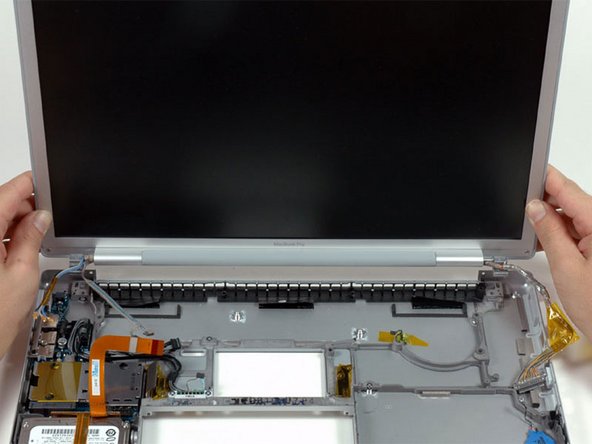
Grasp the display assembly on both sides and lift it up and out of the computer.
-
-
Este passo não foi traduzido. Ajude a traduzi-lo
-
Disconnect the IR and sleep light cables from their connectors above the hard drive.
-
-
Este passo não foi traduzido. Ajude a traduzi-lo
-
Remove the two silver Phillips screws securing the hard drive retaining bracket to the lower case.
-
Lift the hard drive retaining bracket up and out of the computer.
-
-
Este passo não foi traduzido. Ajude a traduzi-lo
-
Lift the hard drive up from the right side and remove it and the attached cable from the computer.
-
-
Este passo não foi traduzido. Ajude a traduzi-lo
-
Remove the following 7 screws/standoffs:
-
Four black T6 Torx screws securing the left I/O board to the lower case.
-
Two silver T6 Torx screws securing the battery connector to the lower case.
-
One 4 mm standoff located between the audio jacks.
-
-
Este passo não foi traduzido. Ajude a traduzi-lo
-
Lift the left I/O board up from the right side and slide it out of the computer.
-
-
Este passo não foi traduzido. Ajude a traduzi-lo
-
Peel up the orange Kapton tape covering the right thermal sensor.
-
Use a spudger to pry the right thermal sensor off the lower case.
-
-
Este passo não foi traduzido. Ajude a traduzi-lo
-
Use a spudger to pry up the PRAM battery off the lower case.
-


Cancelar: não concluí este guia.
19 outras pessoas executaram este guia.
