Esta versão pode conter edições incorretas. Mude para o último instantâneo verificado.
O que você precisa
-
-
Remova os dez parafusos a seguir:
-
Três parafusos Phillips #00 de 14,4 mm
-
Três parafusos Phillips #00 de 3,5 mm
-
Quatro parafusos Phillips #00 com ressalto de 3,5 mm
-
-
-
Com a borda de uma espátula, levante o conector da bateria de seu soquete na placa lógica.
-
-
Este passo não foi traduzido. Ajude a traduzi-lo
-
Use the edge of a spudger to gently pry the fan connector up and out of its socket on the logic board.
-
-
Este passo não foi traduzido. Ajude a traduzi-lo
-
Remove the following three screws securing the fan to the logic board:
-
One 7.2 mm T6 Torx screw
-
Two 5.3 mm T6 Torx screws
-
-
Este passo não foi traduzido. Ajude a traduzi-lo
-
Lift the fan out of its recess in the logic board, minding its cable that may get caught.
-
-
Este passo não foi traduzido. Ajude a traduzi-lo
-
Use the tip of a spudger to pull the right speaker/subwoofer cable out from under the retaining finger molded into the upper case.
-
Pull the right speaker/subwoofer cable upward to lift the connector out of its socket on the logic board.
-
-
Este passo não foi traduzido. Ajude a traduzi-lo
-
Disconnect the following four cables:
-
AirPort/Bluetooth cable
-
Optical drive cable
-
Hard drive cable
-
Trackpad cable
-
-
-
Este passo não foi traduzido. Ajude a traduzi-lo
-
Use your fingernail to flip up the retaining flap on the keyboard ribbon cable ZIF socket.
-
Use the tip of a spudger to pull the keyboard ribbon cable out of its socket.
-
-
Este passo não foi traduzido. Ajude a traduzi-lo
-
If present, remove the small strip of black tape covering the keyboard backlight cable socket.
-
-
Este passo não foi traduzido. Ajude a traduzi-lo
-
Use the tip of a spudger or your fingernail to flip up the retaining flap on the keyboard backlight ribbon cable ZIF socket.
-
Pull the keyboard backlight ribbon cable out of its socket.
-
-
Este passo não foi traduzido. Ajude a traduzi-lo
-
Use the flat end of a spudger to pry the sleep sensor/battery indicator connector up from its socket on the logic board.
-
-
Este passo não foi traduzido. Ajude a traduzi-lo
-
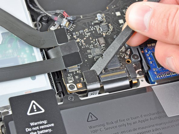
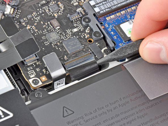
Grab the plastic pull tab secured to the display data cable lock and rotate it toward the DC-In side of the computer.
-
Pull the display data cable straight out of its socket on the logic board.
-
-
Este passo não foi traduzido. Ajude a traduzi-lo
-
Remove the following nine screws:
-
Five 3.6 mm T6 Torx screws
-
Two 4.3 mm T6 Torx screws
-
Two 7.2 mm T6 Torx screws
-
Five 3.0 mm T6 screws
-
Two 3.6 mm T6 screws
-
Two 6.7 mm T6 screws
-
-
Este passo não foi traduzido. Ajude a traduzi-lo
-
Remove the following two screws:
-
One 8.6 mm Phillips screw
-
One 5.5 mm Phillips screw
-
Remove the display data cable retainer from the upper case.
-
-
Este passo não foi traduzido. Ajude a traduzi-lo
-
Use the tip of a spudger to gently peel the microphone off the adhesive securing it to the upper case.
-
-
Este passo não foi traduzido. Ajude a traduzi-lo
-
Minding the many connectors near its edges, lift the logic board from the end nearest the optical drive.
-
Without flexing the board, maneuver it out of the upper case, minding the flexible connection to the DC-In board that may get caught in the upper case.
-
Remove the logic board.
-
-
Este passo não foi traduzido. Ajude a traduzi-lo
-
De-route the microphone cable from its slot molded into the left speaker enclosure.
-
-
Este passo não foi traduzido. Ajude a traduzi-lo
-
Remove the small piece of black tape covering the left speaker connector.
-
-
Este passo não foi traduzido. Ajude a traduzi-lo
-
Use the flat end of a spudger to pry the left speaker connector up from its socket on the logic board.
-
-
Este passo não foi traduzido. Ajude a traduzi-lo
-
Carefully pry the left speaker off the foam adhesive securing it to the logic board.
-
Remove the left speaker.
-
-
Este passo não foi traduzido. Ajude a traduzi-lo
-
Remove the piece of black tape covering the microphone connector.
-
-
Este passo não foi traduzido. Ajude a traduzi-lo
-
Pull the microphone cable upward to lift its connector out of the socket on the logic board.
-
Remove the microphone.
-
-
Este passo não foi traduzido. Ajude a traduzi-lo
-
Pull the MagSafe DC-In board cable toward the heat sink to disconnect it from the logic board.
-
Remove the DC-in board.
-
-
Este passo não foi traduzido. Ajude a traduzi-lo
-
Remove the three 8.4 mm #1 Phillips screws securing the heat sink to the logic board.
-
Carefully remove the heat sink from the processor.
-
-
Este passo não foi traduzido. Ajude a traduzi-lo
-
Pull the two RAM retaining arms away from the center of the RAM chip.
-
Pull the RAM stick out of its socket.
-
Logic board remains.
-
Cancelar: não concluí este guia.
231 outras pessoas executaram este guia.
15 comentários
I decided to take out the logic board because I had a water problem. As you can problably guess all the componentes from both sides of the board, near the ventilation, were dirty with some green and white stuff so I cleand it all up with isopropilic alcohol. I assembeled it buck up and it turns on but it doesnt run the osx, screen doesnt turn on, you cant hear the welcome sound every time you turn on a mac and the only thing you can hear is the fan spinning faster and faster until it reaches its top speed and it stays like that. what can I do to fix it??
Three years later, the answer is that you need to reset your SMC.
ROBOLOBO -
is it possible to assemble the laptop completely without the unibody enclosure?
Yes you can, but it would be unsafe for the macbook
Ryan -
Thanks for this!
Yesterday I embarked upon replacing the keyboard in mine for the 2nd time, and ripped out one of the connectors! After pouring over schematics, the board layout, etc. this guide told me exactly what connector it was; the webcam! This means I won’t be replacing it, since I run Linux the webcam drivers would not work anyway. This saves me a massive headache, microsoldering (Louise Rossman style) and probably breaking more things.


