Esta versão pode conter edições incorretas. Mude para o último instantâneo verificado.
O que você precisa
-
-
Remova os dez parafusos a seguir:
-
Três parafusos Phillips #00 de 14,4 mm
-
Três parafusos Phillips #00 de 3,5 mm
-
Quatro parafusos Phillips #00 com ressalto de 3,5 mm
-
-
-
Com a borda de uma espátula, levante o conector da bateria de seu soquete na placa lógica.
-
-
Este passo não foi traduzido. Ajude a traduzi-lo
-
Use the flat end of a spudger to pry the AirPort/Bluetooth ribbon cable connector up from its socket on the logic board.
-
-
Este passo não foi traduzido. Ajude a traduzi-lo
-
Carefully pull the camera cable out of its socket on the logic board.
-
-
Este passo não foi traduzido. Ajude a traduzi-lo
-
Carefully move the AirPort/Bluetooth ribbon cable out of the way as you peel the camera cable off the adhesive securing it to the subwoofer and the AirPort/Bluetooth bracket.
-
De-route the camera cable out from under the retaining finger molded into the AirPort/Bluetooth bracket.
-
-
-
Este passo não foi traduzido. Ajude a traduzi-lo
-
Use the tip of a spudger to pry the antenna connector closest to the logic board up from its socket on the AirPort/Bluetooth board.
-
De-route the antenna cable from under the finger molded into the AirPort/Bluetooth bracket.
-
-
Este passo não foi traduzido. Ajude a traduzi-lo
-
Using the method described in the last step, disconnect the remaining three antenna connectors.
-
De-route their cables from the slots cut in the AirPort/Bluetooth bracket.
-
-
Este passo não foi traduzido. Ajude a traduzi-lo
-
Remove the following five screws:
-
Two 10.3 mm Phillips screws
-
Two 3.1 mm Phillips screws
-
One 5 mm Phillips screw
-
-
Este passo não foi traduzido. Ajude a traduzi-lo
-
Pull the AirPort/Bluetooth assembly and the Subwoofer upward near the center of the side of the optical drive until they clear each other.
-
-
Este passo não foi traduzido. Ajude a traduzi-lo
-
Remove the AirPort/Bluetooth assembly, minding the fragile antenna contact near the corner of the upper case.
-
-
Este passo não foi traduzido. Ajude a traduzi-lo
-
Remove two of the three 6 mm T8 Torx screws securing the right side of the display to the upper case.
-
-
Este passo não foi traduzido. Ajude a traduzi-lo
-
Grab the plastic pull tab secured to the display data cable lock and rotate it toward the DC-In side of the computer.
-
Pull the display data cable straight out of its socket on the logic board.
-
-
Este passo não foi traduzido. Ajude a traduzi-lo
-
Remove the following two screws:
-
One 8.6 mm Phillips screw
-
One 5.5 mm Phillips screw
-
Remove the display data cable retainer from the upper case.
-
-
Este passo não foi traduzido. Ajude a traduzi-lo
-
Remove the piece of foam tape covering the display screws near the MagSafe DC-In board.
-
-
Este passo não foi traduzido. Ajude a traduzi-lo
-
Remove two of the three 6 mm T8 Torx screws securing the left side of the display to the upper case.
-
-
Este passo não foi traduzido. Ajude a traduzi-lo
-
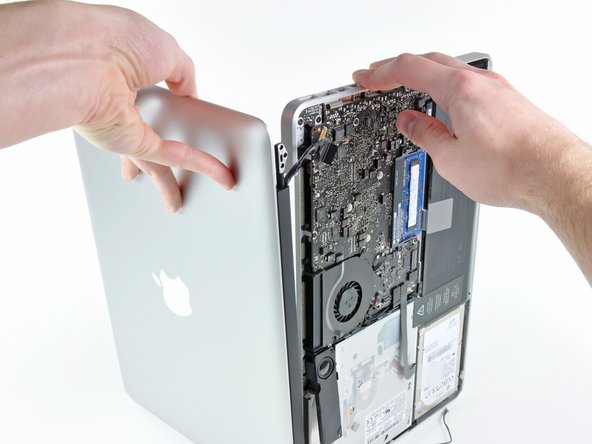
Open your MacBook Pro so the display is perpendicular to the upper case.
-
Place your opened MacBook Pro on a table as pictured.
-
While holding the display and upper case together with your left hand, remove the remaining T8 Torx screw from the lower display bracket.
-
-
Este passo não foi traduzido. Ajude a traduzi-lo
-
Remove the last remaining T8 Torx screw securing the display to the upper case.
-
-
Este passo não foi traduzido. Ajude a traduzi-lo
-
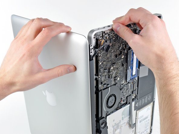
Grab the upper case with your right hand and rotate it slightly toward the top of the display so the upper display bracket clears the edge of the upper case.
-
Rotate the display slightly away from the upper case.
-
Lift the display up and away from the upper case, minding any brackets or cables that may get caught.
-


Cancelar: não concluí este guia.
260 outras pessoas executaram este guia.

26 comentários
No the connector in the logic board/video cable is slightly different.
Correct that the LVDS connectors are slightly different but you can modify them to fit using nail clippers if you are very careful!