Esta versão pode conter edições incorretas. Mude para o último instantâneo verificado.
O que você precisa
-
Este passo não foi traduzido. Ajude a traduzi-lo
-
Remove the soft padding that may be on top and gently pull the connector up out of its socket on the logic board.
-
-
Este passo não foi traduzido. Ajude a traduzi-lo
-
Pull the camera cable connector toward the optical drive to disconnect it from the logic board.
-
-
Este passo não foi traduzido. Ajude a traduzi-lo
-
Use the flat end of a spudger to pry the optical drive connector straight up off the logic board.
-
-
-
Este passo não foi traduzido. Ajude a traduzi-lo
-
Use the flat end of a spudger to pry the hard drive connector straight up off the logic board.
-
-
Este passo não foi traduzido. Ajude a traduzi-lo
-
Remove the following screws securing the subwoofer to the upper case:
-
One 3.8 mm Phillips screw
-
One 5 mm Phillips screw
-
-
Este passo não foi traduzido. Ajude a traduzi-lo
-
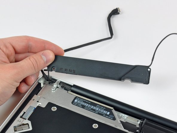
Lift the subwoofer off the optical drive, and set it above the computer.
-
-
Este passo não foi traduzido. Ajude a traduzi-lo
-
Remove the two 10 mm Phillips screws securing the camera cable bracket to the upper case.
-
Lift the camera cable bracket out of the upper case.
-
-
Este passo não foi traduzido. Ajude a traduzi-lo
-
Remove the three 2.5 mm Phillips screws securing the optical drive to the upper case.
-
Lift the optical drive from its right edge and pull it out of the computer.
-


Cancelar: não concluí este guia.
Uma outra pessoa concluiu este guia.

Um comentário
Bonsoir. Le tuto est très clair, mais je voudrais savoir s’il est applicable sur la version 15” du MBP 10. Amicalement, Marc.