Esta versão pode conter edições incorretas. Mude para o último instantâneo verificado.
O que você precisa
-
-
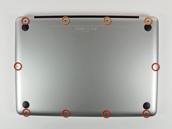
Remova os 10 parafusos a seguir que fixam a estrutura inferior ao MacBook Pro 13" Monobloco:
-
Sete parafusos Phillips de 3 mm.
-
Três parafusos Phillips de 13,5 mm.
-
-
-
Levante ligeiramente a estrutura inferior e empurre-a em direção à parte traseira do computador para liberar as linguetas de montagem.
-
-
Este passo não foi traduzido. Ajude a traduzi-lo
-
Use the flat end of a spudger to lift the battery connector up out of its socket on the logic board.
-
-
Este passo não foi traduzido. Ajude a traduzi-lo
-
Use the flat end of a spudger to pry the subwoofer/right speaker cable connector up off its socket on the logic board.
-
-
Este passo não foi traduzido. Ajude a traduzi-lo
-
Disconnect the camera cable by sliding it horizontally out of its socket.
-
If you see a small plastic retainer stuck to the logic board that prevents the camera cable from sliding out, peel it up carefully from the logic board. Apply a little heat from a hair dryer or heat gun if necessary to help soften the adhesive holding it in place. Do not attempt to forcibly disconnect the cable with the retainer in place.
-
If you still have trouble, use the point of a spudger to push at each side of the connector and "walk" it slowly from its socket.
-
-
Este passo não foi traduzido. Ajude a traduzi-lo
-
De-route the camera data cable from the channel in the optical drive.
-
-
Este passo não foi traduzido. Ajude a traduzi-lo
-
Remove the following screws securing the camera data cable and right speaker to the upper case:
-
Two 8 mm Phillips screws.
-
One 4mm Phillips screw.
-
Slide the camera cable bracket out from under the subwoofer and remove it from the computer.
-
-
-
Este passo não foi traduzido. Ajude a traduzi-lo
-
Grab the plastic pull tab secured to the display data cable lock and rotate it toward the DC-in side of the computer.
-
Pull the display data cable connector straight away from its socket.
-
-
Este passo não foi traduzido. Ajude a traduzi-lo
-
Remove the following two screws securing the display data cable bracket to the upper case:
-
One 7 mm Phillips screw.
-
One 5 mm Phillips screw.
-
Lift the display data cable bracket out of the upper case.
-
-
Este passo não foi traduzido. Ajude a traduzi-lo
-
Use your Torx driver to remove the two outer 6.5 mm screws securing each of the two display brackets to the upper case (4 screws total).
-
-
Este passo não foi traduzido. Ajude a traduzi-lo
-
Open your MacBook so the display is perpendicular to the upper case.
-
Place your opened MacBook on a table as pictured.
-
While holding the display and upper case together with your left hand, use your Torx driver to remove the remaining 6.5 mm screw from the lower display bracket.
-
-
Este passo não foi traduzido. Ajude a traduzi-lo
-
Remove the last remaining 6 mm Torx screw securing the display to the upper case.
-
-
Este passo não foi traduzido. Ajude a traduzi-lo
-
Grab the upper case with your right hand and rotate it slightly toward the top of the display so the upper display bracket clears the edge of the upper case.
-
Rotate the display slightly away from the upper case.
-
-
Este passo não foi traduzido. Ajude a traduzi-lo
-
Lift the display up and away from the upper case, minding any brackets or cables that may get caught.
-
-
Este passo não foi traduzido. Ajude a traduzi-lo
-
Grab the clutch cover as shown and slide it toward the right side of the display.
-
-
Este passo não foi traduzido. Ajude a traduzi-lo
-
Gently rock the clutch cover back and forth on its long axis while pulling it away from the display.
-
Do this action along the length of the clutch cover until you can lift it off the framework attaching it to the display.
-
-
Este passo não foi traduzido. Ajude a traduzi-lo
-
Use the tip of a spudger to pry both AirPort antenna connectors out of their sockets on the AirPort board.
-
-
Este passo não foi traduzido. Ajude a traduzi-lo
-
Remove the four 3 mm Phillips screws securing the antenna bracket to the display.
-
-
Este passo não foi traduzido. Ajude a traduzi-lo
-
Remove the AirPort antenna from the display, minding the antenna connectors that might get caught.
-
Cancelar: não concluí este guia.
36 outras pessoas executaram este guia.
3 comentários
How can i translate this guide to Portuguese? when i click in "options" then "translate" Portuguese is non accessible.


