Esta versão pode conter edições incorretas. Mude para o último instantâneo verificado.
O que você precisa
-
-
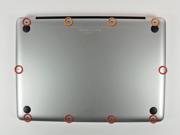
Remova os 10 parafusos a seguir que fixam a estrutura inferior ao MacBook Pro 13" Monobloco:
-
Sete parafusos Phillips de 3 mm.
-
Três parafusos Phillips de 13,5 mm.
-
-
-
Levante ligeiramente a estrutura inferior e empurre-a em direção à parte traseira do computador para liberar as linguetas de montagem.
-
-
Este passo não foi traduzido. Ajude a traduzi-lo
-
Use the flat end of a spudger to lift the battery connector up out of its socket on the logic board.
-
-
Este passo não foi traduzido. Ajude a traduzi-lo
-
Use a spudger to pry the fan connector out of its seat, and straight up off the logic board.
-
-
Este passo não foi traduzido. Ajude a traduzi-lo
-
Remove the following three screws securing the fan to the upper case:
-
One 6.5 mm Phillips.
-
One 5.5 mm Phillips.
-
One 4.5 mm Phillips.
-
-
Este passo não foi traduzido. Ajude a traduzi-lo
-
Grab the plastic pull tab secured to the display data cable lock, and rotate it toward the DC-in side of the computer.
-
Pull the display data cable connector straight away from its socket, towards the DC-in side of the computer.
-
-
-
Este passo não foi traduzido. Ajude a traduzi-lo
-
Remove the following two screws securing the display data cable bracket to the upper case:
-
One 7 mm Phillips.
-
One 5 mm Phillips.
-
Lift the display data cable bracket out of the upper case.
-
-
Este passo não foi traduzido. Ajude a traduzi-lo
-
Use the flat end of a spudger to pry the subwoofer and right speaker connector up off the logic board.
-
-
Este passo não foi traduzido. Ajude a traduzi-lo
-
Pull the camera cable connector toward the optical drive to disconnect it from the logic board.
-
-
Este passo não foi traduzido. Ajude a traduzi-lo
-
Use the flat end of a spudger to pry the optical drive, hard drive, and trackpad cable connectors up off the logic board.
-
-
Este passo não foi traduzido. Ajude a traduzi-lo
-
Use your fingernail or the tip of a spudger to flip up the cable retaining flap on the ZIF socket for the keyboard ribbon cable.
-
Use your spudger to slide the keyboard ribbon cable out of its socket.
-
-
Este passo não foi traduzido. Ajude a traduzi-lo
-
Peel the small strip of black tape off the keyboard backlight ribbon cable socket.
-
-
Este passo não foi traduzido. Ajude a traduzi-lo
-
Use the tip of a spudger to flip up the cable retaining flap on the ZIF socket for the keyboard backlight ribbon cable.
-
Use your spudger to slide the keyboard backlight ribbon cable out of its socket.
-
-
Este passo não foi traduzido. Ajude a traduzi-lo
-
Use the flat end of a spudger to pry the battery indicator cable connector up off the logic board.
-
-
Este passo não foi traduzido. Ajude a traduzi-lo
-
Use the tip of a spudger to pry the microphone off the adhesive attaching it to the upper case.
-
-
Este passo não foi traduzido. Ajude a traduzi-lo
-
Remove the following screws:
-
Five 3.1 mm Phillips.
-
Two 3.9 mm Phillips.
-
Two 7 mm Phillips from the DC-in board.
-
-
Este passo não foi traduzido. Ajude a traduzi-lo
-
Remove the following Tri-point screws securing the battery to the upper case:
-
One 5.5 mm Tri-point screw.
-
One 13.5 mm Tri-point screw.
-
Lift the battery out of the upper case.
-
-
Este passo não foi traduzido. Ajude a traduzi-lo
-
Lift the logic board from its left edge and raise it until the ports clear the side of the upper case.
-
Pull the logic board away from the side of the upper case and remove it, minding the DC-in board that may get caught.
-
-
Este passo não foi traduzido. Ajude a traduzi-lo
-
Disconnect the DC-In board by pulling its connector away from the socket on the logic board.
-
Cancelar: não concluí este guia.
89 outras pessoas executaram este guia.
5 comentários
Reassembling: Make sure, the cable of the DC-In board is on the logic board-side of the screw hole when putting in the logic board. Otherwise the display data cable bracket won't fit in and you have to remove the board again.
So I hope, the DC-In board was really the cause of my problems. I changed the battery and the charging cable before and still had problems. At this moment my macbook loads again, but I don't know if its because of the board or again just luck. Thank you very much for the guide.
Many thanks for this great manual. You helped me to prolong my old MacBook’s life and I saved a lot of money. Carry on the good work!
Any possibilities to also show “how to upgrade the mother board”?


