Esta versão pode conter edições incorretas. Mude para o último instantâneo verificado.
O que você precisa
-
Este passo não foi traduzido. Ajude a traduzi-lo
-
Remove the following ten screws securing the lower case to the upper case:
-
Two 2.3 mm P5 Pentalobe screws
-
Eight 3.0 mm P5 Pentalobe screws
-
-
Este passo não foi traduzido. Ajude a traduzi-lo
-
Wedge your fingers between the upper case and the lower case.
-
Gently pull the lower case away from the upper case.
-
Remove the lower case and set it aside.
-
-
Este passo não foi traduzido. Ajude a traduzi-lo
-
The lower case is connected to the upper case at the center, with two plastic clips.
-
-
Este passo não foi traduzido. Ajude a traduzi-lo
-
Remove the plastic cover adhered to the battery contact board.
-
-
Este passo não foi traduzido. Ajude a traduzi-lo
-
Remove the following screws securing the battery connector board to the logic board:
-
Two 2.8 mm T6 Torx screws
-
One 7.0 mm T6 Torx shouldered screw
-
-
Este passo não foi traduzido. Ajude a traduzi-lo
-
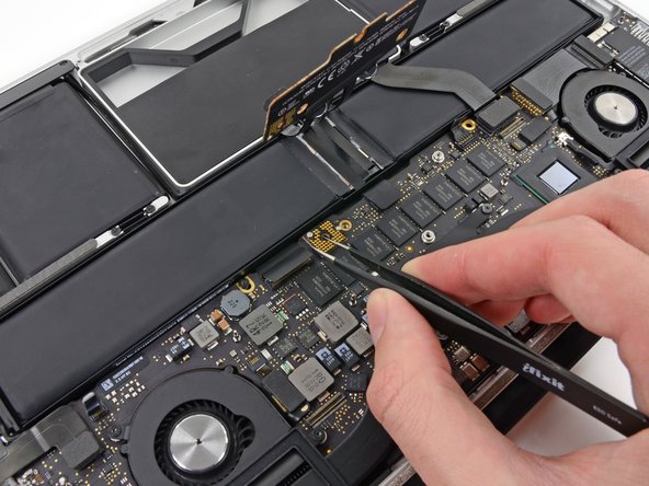
Use tweezers to remove the small plastic cover located near the bottom right of the battery connector board.
-
-
-
Este passo não foi traduzido. Ajude a traduzi-lo
-
Remove the wide head 6.4 mm T6 Torx screw securing the battery connector to the logic board assembly.
-
-
Este passo não foi traduzido. Ajude a traduzi-lo
-
Carefully lift the battery connector board up off the logic board.
-
It is recommended to bend the battery cables just slightly, to keep the board suspended up above the logic board and out of the way.
-
-
Este passo não foi traduzido. Ajude a traduzi-lo
-
Grasp the Interposer with tweezers.
-
Lift the Interposer off the logic board and remove it.
-
-
Este passo não foi traduzido. Ajude a traduzi-lo
-
Use the flat end of a spudger to pry the SSD cable connector up from its socket on the logic board.
-
-
Este passo não foi traduzido. Ajude a traduzi-lo
-
Use your thumb or finger to bend the plastic spring bar on the SSD tray, freeing the two clips at the front side of the device.
-
While holding the spring bar depressed, tilt the SSD assembly up out of its cavity.
-
-
Este passo não foi traduzido. Ajude a traduzi-lo
-
Remove the single 2.9 mm T5 Torx screw securing the SSD to the SSD tray.
-
-
Este passo não foi traduzido. Ajude a traduzi-lo
-
Insert the edge of plastic opening tool between the SSD and the SSD tray, opposite to the socket side of SSD tray.
-
Pry the side of the SSD opposite the SSD tray socket out of the SSD tray.
-
-
Este passo não foi traduzido. Ajude a traduzi-lo
-
Carefully pull the SSD straight out of its socket on the SSD tray.
-
Cancelar: não concluí este guia.
54 outras pessoas executaram este guia.
5 comentários
Excelente, muchas gracias
Ok, now that I replaced my SSD - how do I recover my OS?
You can boot your mac to the recovery pressing command + R while you turn on your mac, configure your wifi and then create the partition in the ssd using disk utility, then you can clos disk utility and proceed to the instalation of the OS, the installation will be downloaded from the apple servers so it will depend of your internet speed how long will it take.
Sieht so aus, als würde da eine ganz normale 2,5”-SSD reinpassen, wenn man den Einschub weglässt. Kann man das Kabel am MBP entfernen und ohne den Einschub benutzen?
Geht leider nicht. Die neue NVMe m.2 SSD muss eine Übergangslösung haben. Leicht zu finden beim Internett. Das Übergang ist ein kleines Zeug das Mann braucht der Länge und Datei - Brikett zur passen.


