Esta versão pode conter edições incorretas. Mude para o último instantâneo verificado.
O que você precisa
-
Este passo não foi traduzido. Ajude a traduzi-lo
-
Remove the following ten screws securing the lower case to the upper case:
-
Two 2.3 mm P5 Pentalobe screws
-
Eight 3.0 mm P5 Pentalobe screws
-
-
Este passo não foi traduzido. Ajude a traduzi-lo
-
Wedge your fingers between the upper case and the lower case.
-
Gently pull the lower case away from the upper case.
-
Remove the lower case and set it aside.
-
-
Este passo não foi traduzido. Ajude a traduzi-lo
-
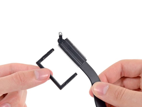
The lower case is connected to the upper case at the center, with two plastic clips.
-
-
Este passo não foi traduzido. Ajude a traduzi-lo
-
Remove the plastic cover adhered to the battery contact board.
-
-
Este passo não foi traduzido. Ajude a traduzi-lo
-
Remove the following screws securing the battery connector board to the logic board:
-
Two 2.8 mm T6 Torx screws
-
One 7.0 mm T6 Torx shouldered screw
-
-
-
Este passo não foi traduzido. Ajude a traduzi-lo
-
Use tweezers to remove the small plastic cover located near the bottom right of the battery connector board.
-
-
Este passo não foi traduzido. Ajude a traduzi-lo
-
Remove the wide head 6.4 mm T6 Torx screw securing the battery connector to the logic board assembly.
-
-
Este passo não foi traduzido. Ajude a traduzi-lo
-
Carefully lift the battery connector board up off the logic board.
-
It is recommended to bend the battery cables just slightly, to keep the board suspended up above the logic board and out of the way.
-
-
Este passo não foi traduzido. Ajude a traduzi-lo
-
Grasp the Interposer with tweezers.
-
Lift the Interposer off the logic board and remove it.
-
-
Este passo não foi traduzido. Ajude a traduzi-lo
-
Remove the following screws securing the heat sink to the logic board assembly:
-
One 2.4 mm Phillips #00 screw
-
One 3.4 mm T5 Torx screw
-
Four 2.7 mm T5 Torx screws
-
-
Este passo não foi traduzido. Ajude a traduzi-lo
-
Lift and remove the heat sink up off the logic board assembly.
-
-
Este passo não foi traduzido. Ajude a traduzi-lo
-
Carefully remove the right fan duct from the edge of the heat sink.
-
-
Este passo não foi traduzido. Ajude a traduzi-lo
-
Carefully remove the left fan duct from the edge of the heat sink.
-


Cancelar: não concluí este guia.
7 outras pessoas executaram este guia.

