Introdução
Use this guide to replace the display assembly of your non-Touch Bar MacBook Pro (13-inch, 2017, Two Thunderbolt 3 ports).
Before starting this procedure, you may want to check with Apple to see if you qualify for a free repair. If your display’s backlight has stopped working, or the display shows vertical bright areas along the entire bottom of the screen (a.k.a. “stage lights”), your MacBook Pro may be eligible for Apple’s display backlight service program.
For your safety, drain your MacBook Pro's battery below 25% charge before starting repairs.
O que você precisa
-
-
Power on your Mac and launch Terminal.
-
Copy and paste the following command (or type it exactly) into Terminal:
-
sudo nvram AutoBoot=%00
-
Press [return]. If prompted, enter your administrator password and press [return] again. Note: Your return key may also be labeled ⏎ or "enter."
-
sudo nvram AutoBoot=%03
-
-
-
Use a P5 Pentalobe driver to remove the six screws securing the lower case:
-
Two 6.2 mm screws
-
Two 5.3 mm screws
-
Two 3.4 mm screws
Before any repair is carried out that involves removing the bottom case, the machines auto-boot function has be disabled. This can be disabled via the terminal command “sudo nvram AutoBoot=%00” once the repair has been completed the auto-boot function can be re-enabled via the vermin command “sudo nvram AutoBoot=%03”.
I recommend that you have an organizer tray for all the small parts, and label it in advance with the numbered “step” associated with each removal of screws and other parts. It really helped me when I needed to put everything back in reverse order, after the new battery is glued in place.
Finished the repair last week. Some key comments that helped me:
- Step 12, Robert
- Step 13, MikeG1
- Step 13, Rick Jaffe (take a photo when disassembling)
Also added some own comments on Steps 15, 18, 22
-
-
-
Apply a suction handle to the lower case near the front-center area of the MacBook Pro.
-
Lift the suction handle to create a slight separation between the lower case and the chassis.
To replace the bottom just line it up just like it came from the factory. Make sure it clears the display connectors. And press firmly down until the clips connect to the bottom again.
-
-
-
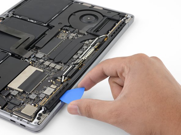
Insert your opening pick once again under the front edge of the lower case, near one of the two centermost screw holes.
-
Give the pick a firm twist to pop free the third clip securing the lower case to the chassis.
-
Repeat this procedure near the other of the two centermost screw holes, popping the fourth clip free.
My 3rd and 4th clips released simultaneously with clip 1 and 2.
Therefore I was looking to do something which had already been accomplished.
yeah be sure not to bend those clips by the display bottom. You pull towards yourself to get it off
-
-
-
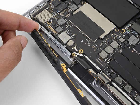
Pull the lower case firmly towards the front of the MacBook (away from the hinge area) to separate the last of the clips securing the lower case.
Difficult to explain clearly, but worked easily for me by gripping the adjacent bottom and top corners then pulling in opposite directions, rather than trying to grip the hinge corner which is too narrow to afford a strong grip.
This helped me. It needed more force than what I expected. Basically grab the corner with 6.2mm screw with one hand and the cover of that same corner with the other. Then pull the cover and push the laptop. Careful, it pops off with force!
I initially tried shifting the whole panel off the front after using the separating tool to make some space at the back where the hinges are. I only had luck when I pushed the panel back to it’s normal state and using the separating tool again to open the front, then getting my fingers underneath the slide it off the front was easy. I guess the lesson is to not use the separating tool to “push from the back“.
This step really through me through a loop. My last two MBP were a 2011 and 2013 and on those the bottom just lifted off when you removed the screws. The clips and this sliding lock design added in the 2017 model was frustrating the first time. I was following a youtube video first and he did not explain the sliding part at all. I should have come here first, this guide explains it pretty well. The second time I opened my 2017, I kept an “opening pick” between the bottom panel and the body on each side, and used my two smallest screwdrivers as levers in both “front” corner screw holes. Used the same method without the picks to put it back together at the end. Wayyy easier that trying to grip the panel or laptop body. Just make sure the screwdrivers/pins that you’re using as levers are small enough to be loose in the screw holes and have room to move
I used a pick underneath one of the back corners and nudge it (push down and towards the front - to get it off the hinge). This will make it easier to do the same for the other corner. The lower case will move off the middle plastic L-clips (which you will see after you inspect it.) Cheers! =)
I have found that your iFixit blue pry tool is excellent at giving me leverage to slide the bottom case forward to release it from the internal clips.
-
-
-
Remove the lower case.
I used the green prying tool in the air gap at the rear to nudge the bottom forward.
That is far easier and more reliable.
David. I agree. I've found the blue iFixit prying tool most helpful. I place it with the curve of the tool around the hinge and move the bottom case towards the front to release it from the slide-in clips. I consider myself to have pretty good grip strength but I have had some bottom cases that just wouldn't budge until I used this method. Scott The Mac Doctor
Like Dave and "themacdoctor" said, this job is MUCH easier if you use a spudger or similar tool to gently push the cover away from the air gap, at the rear of the laptop. Once you do this, you've loosened clips that are on the inside of the bottom case. This is much easier than tugging on the case itself.
-
-
-
Carefully peel up the large piece of tape covering the battery connector, on the edge of the logic board nearest the battery.
-
Remove the tape.
once the tape's back in place, it doesn't look tightly attached. not sure, did I do something wrong here or it should be so.
The tape will likely not adhere as well as when it came out of the factory. This isnt an issue! As long as the tape is in place when the lower cover is put back on the device you should be good to go.
The underside of the tape is not uniform. Therefore, pay attention to which direction it is placed by looking at the underside when you remove it. Possibly mark one edge so that you can replace in the same direction during reassembly.
Mark one of the tape’s edges and, upon removal, stick it down with the same orientation. The first time I was inside the MacBook Pro (to upgrade the SSD) I failed to do this, and spent almost 30 minutes trying to get it back like it had been. Making a photo also helps.
-
-
-
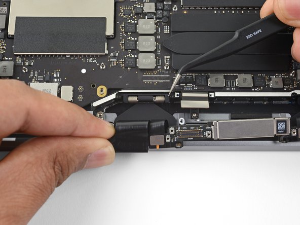
Gently peel back the small piece of tape covering the battery board data cable connector.
-
-
-
-
Use the tip of a spudger to flip up the small black locking tab securing the cable in its connector.
-
-
-
Disconnect the battery board data cable by sliding it out from its socket.
-
Slide parallel to the logic board, in the direction of the cable.
The little tab that you pull back on, at least in my cable, was simple glued onto the rest of the cable. I tried to carefully remove the cable, and the tab came off. I did not have flat tweezers in the ifixit replacement kit and did not want to pinch the cable with sharp instruments. Therefore, be extremely careful when removing the tab as it is difficult to reattach the cable without it.
-
-
-
Fold the battery board data cable back and out of the way.
The new battery I received did not come with the battery board data cable, so I had to remove the existing one and transfer it. The lock at the smaller end is the same mechanism as the one at the end shown in steps 11 and 12, but smaller (and harder to see. It helps to gently straighten the left end of the cable before trying to insert it in the end of the replacement circuit board.
I can corroborate MikeG1’s comment. My battery came without the long data cable as well. I had to remove it from the fried battery. Plastic lock tab mechanism on the ZIF connector is smaller. My inspection microscope helped to transfer the cable to the new battery board. Thanks Mike!
Likewise - the new battery came without a data cable. The cable was successfully removed from the old battery assembly and installed on the new battery, but it was tricky and nerve-racking (the cable is delicate and the connectors are very small) without instruction provided! The instructions should be updated to highlight the missing cable possibility, and provide information/illustration on transferring the cable.
In step 13, notice the amount of the data cable that sticks out of the connector. When moving this cable to the new battery, it is difficult to tell how far to push the cable into the connector or when it is fully inserted because the cable is so bendable.
AMEN!! This was the hardest part of the ENTIRE process! Hard to know when the small end of the cable was “fully” inserted. Cable is SOOOOO delicate!
my old battery was working but could not hold a charge very long so I replaced the battery and now my mac does not recognize the new battery. Thought it was a bad battery at first but I purchased a new batter and still the same problem, My mac will work off power outlet but does not register it has a battery at all now. I tried putting my old battery back on but i damaged the very small clip when i slid out the flex cable so its gone now. Could this cable be at fault? I don/t know what else it could be, i only messed with the battery.
I have this same problem! Did you figure out what the issue was? Do I need a new flex cable?
I am having the same issue as Leo. After install. Is there a way to identify the fault?
Although the rest of fixit manual on this is excellent, this step is woefully lacking and the fact that the replace “kit” doesn’t have the Battery Board Data cable included makes the replacement kit significantly lacking (especially compared to other kits and instructions I’ve used before from them)
-
-
-
Use a T5 Torx driver to remove the 3.7 mm pancake screw securing the battery power connector.
When the battery management “BMS” circuit board is re-installed, loosely install the two 3.7 mm screws, put a spudger on the left side of the BMS board to wedge theBMS board to the right then tighten the two 3.7 mm screws. The reason for doing this is that the two power traces on the board may not make physical contact with the battery connector (connector at where the spudger is on step 15). One clue that you didn’t have physical contact is if you reinstalled everything but there is no power unless the AC supply is plugged in (with battery meter on the top at 0%). This was what happened to me. The reason is that when you bend the battery connector in step 15, it’s no longer in alignment with the traces on the BMS board and hence, you have to shift the BMS board to the right to compensate. Once I did this, voila 64% power.
-
-
-
Use a spudger to gently lift the battery power connector, disconnecting the battery.
-
Lift the connector high enough so that it stays separated from its socket. If it accidentally makes contact during the course of your repair, it could damage your MacBook Pro.
On disassembly note the position of the connector before you lift. It has two gold-plated connections on the underside. On reassembly these need to make contact with the matching battery board connectors. Bending the connector out of the way deformed it a bit, and on reassembly I could see that the connectors didn't align well with the board's connectors. I needed to adjust the battery board position to the left a bit by loosening the 3.1 mm screws in step 23. Possibly this could be the reason why some people report that new battery is not detected.
-
-
-
Remove the four 1.9 mm T3 Torx screws securing the plastic covers on top of the display hinges.
-
Remove both plastic hinge covers.
Be careful tightening these screw. Overtightening will shear the heads off of them.
When reinstalling the plastic hinge covers, be sure to slide the bottom portion UNDER the rim of the unibody. If not when you go to reattach the bottom, it will not fully mate to the body.
-
-
-
Remove the two 2.9 mm T3 Torx screws securing the aluminum cover on top of the main display cable.
-
Remove the cover.
For me, the left one (on image) are T3 and the right are T4! haha… I’ll put a pic here to show you guys LOL
-
-
-
Remove the two 1.7 mm T3 Torx screws securing the aluminum cover on top of the display cable flex connector.
-
Remove the cover.
I had a hard time getting a T4 bit to go into the one on the left, T3 worked perfectly. The one on the right the T4 bit fit just fine.
Impossible for me to take out these screws.
Can confirm, these are T4 for me, my T3 driver is just spinning inside
T3 for me...
-
-
-
Pry the display board flex cable straight up from its socket to disconnect it from the display board.
It actually clicks on and off—I did not pay attention when installing the new monitor and when I went to start the computer the screen did not have power but the bottom half came on (the hard drive fan went brrrr) this connector was down—but I had not “clicked” it on. It can be installed such that it will stay on without the metal strip that goes across it. The metal strip seems to be just to ensure it *stays* on. You got this!
-
-
-
Remove the four 1.5 mm T3 Torx screws securing the two aluminum covers on top of the two display cables.
-
Use a pair of tweezers to remove the two aluminium covers.
These are mirror images of each other! Beware! In the photo you’ll see that in reassembly the “extra” metal bit goes toward the front. If you look at the underside of them you’ll see two foam bits: one square one to go over the flat metal part, the rectangle over the cable. With the extra metal bit toward the front (away from you) be sure you have the correct cover on the correct side!
This step may be unnecessary if you’re replacing the display. Check on your new display if these are already installed. If they are, skip this step. So far as I can tell, the only reason you do this step is on the off chance your new display does not have these two covers, they don’t really do anything to help remove or install the new display.
Agreed with arichard2401. My replacement display came with both covers. Good idea to always be sure to inspect your replacement before beginning.
-
-
-
Remove the two 3.3 mm T5 Torx screws (one from each side) securing the antenna cable assembly.
-
Also remove the two 4.1 mm T5 Torx screws (one from each side).
-
Remove the twelve 1.1 mm P2 pentalobe screws (six from each side) securing the rest of the antenna cable assembly.
Un reassembly, DONT OVERLOOK the placement of the “Board Flex Cable” from step 19. Make sure you don’t leave it imprisoned under this assembly. It needs to be lying over all this assembly.
When reinstalling the antenna cable assembly, on the front side of it facing towards the trackpad, there is a flat silver piece of metal. It needs to go into a little track in the MacBook. If it doesn’t, things will seem normal until you go to close the lid, and you will get a click.
The screw drives of the P2 screws are extremely weak. Be careful when removing these screws and putting them back in.
Those 12 tiny screws are a frickin’ nightmare. They appear to be P1’s, not P2’s , as all I have are a P0.8 and a P1.2, and the 0.8 just strips the heads. I did manage to get one out, but that’s it so far. I’m think I’m going to have to use my Dremel to make a slot for a tiny flat bit to get them out… Grrrr…
i had a horrible time trying to get the 12 p2 screws out and i was ready to give up. i finally got them out when i applied really hard downward pressure onto my screwdriver. i really dug the end of my screwdriver into my palm. put some weight into it.
Oh man, be so so so so sure you aren’t stripping these tiny little screws. I got all of them out just fine with a P2, but one of them would just not come out and I ended up stripping it. Had to drill it out. Good news is that it will drill out really really easily with a 1/6 bit, just go really slow.
anyone else have little dabs of cement along the 12 lcd cable screws? seems like apple tried to prevent me from doing this when they made it lol. 1/6 “ DRILLING IT IS lol
Maybe I could just drill out the stuck ones and only replace the ones that aren’t super messed up? Is that a stupid idea?
Hi Grant! Yes, that's a valid option.
-
-
-
Carefully disconnect the two antenna coax cables by prying them straight up from the logic board.
-
Slide your tweezers or spudger underneath each cable until it's near the socket, and then gently twist or pry up to disconnect it.
-
-
-
Use an opening pick to lever out the antenna cable assembly in the areas shown.
-
-
-
Carefully remove the antenna assembly, while simultaneously feeding the antenna cable bundle through the hole in the chassis.
-
-
-
Remove the antenna cable assembly.
What is the function of this antenna cable assembly?
The antenna assembly contains the antenna lines for Wi-Fi and Bluetooth. Without the assembly, you'll have terrible Wi-Fi and Bluetooth reception.
During reassembly after I put on the antenna piece the hinge would make a loud snap after being closed from a greater than 90 degree angle. After some trial and error I found a metal piece in the center of the antenna assembly that had to be bent back to fit in a grove in the aluminum of the computer. Hope that helps if someone is having a similar issue.
-
-
-
Remove the four 3.9 mm T3 Torx screws securing the cover springs on the two display cables.
-
-
-
Grab the left side of the display cable assembly and pull it towards the bottom end of the MacBook and away from the cover spring.
-
Use a pair of tweezers to pull the cover spring on the display cable out of its recess.
-
Repeat this step with the right cover spring.
-
-
-
While steadying the MacBook pro with your free hand, remove the three T8 Torx screws from the lower display hinge.
-
Remove the remaining three T8 Torx screws from the upper display bracket.
I don't know if it's been edited, but I'm not seeing that. What I do see is they used 2 different colors for each of the sets of 3, and all six screws are the same.
-
-
-
Push both halves of the MacBook Pro together so that the hinge brackets can be lifted clear of their recesses in the chassis.
-
Push the main body of the MacBook Pro away from you while pulling the screen toward you to separate it.
-
Remove the display/screen assembly, being careful not to snag it on any cables.
During reassembly remember that the screen goes AWAY from you (as in the picture during removal). My cable was taped to the front of the display and had to be untaped and draped backwards over the bottom edge to get into proper position for attachment. Also, just in case this happens to you, too, the longitudinal rod that carries the springs and hinges was about 0.5mm too long to fit into the recesses. I had to file the rod down very slightly to get it to fit.
-


Compare your new replacement part to the original part—you may need to transfer remaining components or remove adhesive backings from the new part before installing.
To reassemble your device, follow the above steps in reverse order.
Take your e-waste to an R2 or e-Stewards certified recycler.
Repair didn’t go as planned? Try some basic troubleshooting or search our Answers community for help.
Cancelar: não concluí este guia.
79 outras pessoas executaram este guia.

23 comentários
This guide sucks really bad.. missed steps. so unclear about everything. crappy pictures, I suggest you re do this whole thing.
Good guide for someone with experience. I would add a few extra steps with more details, including some additional warnings since having a beginner follow this guide could result in failure in repairing the device. PLEASE HAVE SOMEONE WITH EXPERIENCE PERFORM THIS REPAIR!
This worked perfectly and saved me a lot of money. Many thanks.
great tutorial but my webcam stopped working after i replaced the screen… any ideas? also what cable is the camera one?
The same thing happened to me, I used my warranty to get a screen replacement. The camera works fine for now. I'll see how long it holds up.
I am definitely an inexperienced at this stuff. Followed it to replace my sons display. Could not get Genius Bar appointment for a month trying. I found this guide to be perfect. Took me 4 slow patient hours because I knew I would have to reverse the steps when finished , however I finished and my son is so happy. Thank you , Tarun and. IFIXIT.
Whatever has been done to improve this review, I must say, it’s fantastic. Nothing was missed. Brilliant repair guide. Thanks!
I have never taken apart a laptop before and this guide made it a complete success!
My only bit of input is that I found many instances where the T4 tip worked better on screws that the guide called to use T3.
I replaced my broken screen using this guide. Guide is superb. Did not need to watch a video. This was the first time I ever opened a macbook pro.
On the criticism side: I agree with other commenters that steps 17 and 18 requires a T4 torx screwdriver, not T3 as stated in the guide. Additionally, step 29 requires a T8 torx screwdriver, which isn’t listed as a required tool. I happened to have a T8, but this repair could not be completed with the listed tools only.
Thanks again.
That's interesting. I was provided a T8 screw in my repair tool kit.
Nicely done and clear. One possible improvement:
Step 21 now says:
Remove the two 3.3 mm T5 Torx screws (one from each side) securing the antenna cable assembly.
Also remove the two 4.1 mm T5 Torx screws (one from each side).
It should say:
Remove the two 3.3 mm T5 Torx screws (one from each side) securing the antenna cable and display cable assemblies.
Also remove the two 4.1 mm T5 Torx screws (one from each side).
This is not an important change when you are REMOVING those screws, but it’s important when you are re-installing them, because it will encourage you to install the screws onto BOTH the antenna and display cable assemblies…
I'm with brentp — there was absolutely nothing wrong with this guide. I've also used it several times.
The guide made it easy the tiny screws made it tedious and the magnetic tools made it all possible.
When removing the P2 tiny screws from the antenna assembly, make sure you press firmly and twist very slowly first, in order to avoid stripping your P2 driver, which can happen very easily. We've lost a couple to this already, and we use them to open iPhones too, so take care of them! Also if you break your P2 tip in the middle of this job and you have none other, you're literally SCREWED! hahaha :)
Great guide, and it covered everything in a simple and easy to understand way!
My only critique is that step 20, removing the display cover cables is unnecessary. Unless the replacement display assembly didn't come with those.
I think you need to since they're screwed down. Otherwise, I don't see how else the display covers would come off. I had to unscrew the covers to unhinge the display springs in order to remove the screen since they're attached.
I agree. I have used these instructions twice, and each time was successful. The only thing I would suggest iFixit is to add to the kit is a magnetic mat for all the screws placement, so nothing is lost nor forgotten where each one goes.
This guide worked great for me. Reading through the comments on the various steps was beneficial. There were a couple points where I needed to use a T4 screwdriver tip vs the T3 tip mentioned, but other than that, all the steps are clear and the photos a great help.
Can you provide help and easy way to replace screen
Is this step necessary? I can’t perform this step as I am attempting to repair water damage and need to remove logic board & most likely replace the battery.
Macrepair SF - Responder
@mac_medic You definitely don’t want the power coming on while the board is wet. In your case, I think powering on the machine to disable Auto Boot would do more damage than it prevents. I agree, skip this step and be prepared to disconnect the battery quickly if the laptop automatically powers on. Good luck!
Jeff Suovanen -
Thats right! You don't want power running while working on your logic board.
Dan -
This did not work when running High Sierra.
Kyle B - Responder
Tried this on a 2018 MBP 13” Touchbar (there’s no iFixit guide for this model yet). Need to replace a broken screen.
Luckily I managed to connect to an external screen (Cmd-Down Brightness to switch displays) and enter above command. Seems to work, but there’s another problem with this model - it powers up as soon as any key is pressed……. ffs <gnashes teeth>
Cool_Breeze - Responder
I unscrew the battery first and wrap electrical tape over the logic board battery connector before attempting any repairs to the board. Haven’t had any problems yet and I’ve worked on about 10 of these models already. Also when you open the bottom case use a suction cup at the bottom and pull up then run a plastic spudger along the edges to disconnect the clips. Also only use a plastic spudger on the board. Saw a youtube video from a repair shop and he did not disconnect the power and used all metal tools during the entire process of removing the board. His last step was to disconnect the battery terminal.
Brian - Responder
Is this step necessary if my mac can turn on? Battery fully dead(
Nursat b - Responder
BEFORE YOU START: The included torx head stripped off before I was done (and you might need an additional T4) so stop now and go buy a good one. Also they fail to warn you above to get some blue threadlocker ahead of time.
Jason Sherron - Responder
This command did not work for me and I read that sometime in later 2020 Apple stopped this command from working…any ideas on a work around?
Patrick Machacek - Responder
Not able to do that with damaged screen
richardjgreen - Responder
If you have a damaged screen you can still use a converter from thunderbolt (USB 3) to HDMI and plug your Macbook Pro to your TV as monitor display. Just make sure to chose the right Source (HDMI IN) in your TV. I did it and to make it work I unplug and plug again in my Macbook and so I could disable the Auto boot
Roberto Sanchez Bustos -
Hi. This does not work on 2018 13” MacBook Pro with Touch Bar. I did exactly this to disable auto boot. But when I check by using nvram -p it says: auto-boot true. Am I doing something incorrectly? I did everything step by step. Copied and pasted the sudo command, pressed enter and then entered my password. I have Big Sur 11.1 installed. Is there any other way since I need to replace the screen. Thank you. Adrian
Adrian Vizik - Responder
Hi everyone. This is also a little pointless if you can’t see anything on the screen, and you don’t have a display adapter to USB C to display it. I agree with Brian about removing the back and disconnecting the battery cable before you even think about opening the lid of the MacBook. Applying the insulation tape is also a handy little tip that just makes sure there is no way to discharge from either the board or battery.
Roberto Enrieu - Responder
running `nvram -p | grep 'AutoBoot'` in terminal verifies that it was accepted
result: `AutoBoot %00`
Marek Polák - Responder
Running Big Sur 11.6.7 on a 2019 16" MBP, it's "auto-boot". So it's:
nvram -p | grep 'auto-boot'to display the current state, the default istrue- and then to change it,sudo nvram auto-boot=falsewhich turns it off.Ed Mechem -
This step is completely unnecessary if you follow the guide to disconnect the battery properly. Just put some tape between the battery and logic board connection to prevent it from accidentally touching and therefore powering on the laptop.
Grant Ormsby - Responder
It took me a few tries to make this command work, as I was able to copy and paste the command into Terminal, but could not type in my laptop’s password. I finally typed my password into a text document, copied it (command C), and then pasted it into Terminal and it worked.
tommy404 - Responder
I didn’t do this. Mine never auto-booted before I replaced the battery. Now it does.
hatuxka - Responder
BEFORE YOU DO ANYTHING - CHECK THE BATTERY!
I-fixit sent me a bad battery, which I didn’t realize until it was already install. They sent me a new one, but I wasted hours uninstalling and reinstalled.
Get a volt meter and measure the voltage on the output of the battery pack. If it reads 0 V, SEND IT BACK. It should read over 2 V.
bcardanha - Responder
I've just received my replacement battery and it reads 0,042V between the two main connectors. Do you think it's dead?
peter sussex -
When I did this from Terminal.app within Recovery Mode, the “sudo” was not recognized but I could invoke it without the sudo part. It seems to have been accepted when looking at “nvram -p”
johann beda - Responder
When in Recovery Mode, you already have superuser powers. So you don't need to prefix commands with the sudo command to invoke them with root privileges; you already have them. Do a
pwd(print working directory) after opening Terminal in Recovery Mode, and you'll see that you're in the root user's directory.Ed Mechem -
I received the battery kit for my 2018 MacBook Pro and as per the above comment from bcardanha - Oct 12, 2021, I checked the voltage on the pads marked + and - . It was zero volts so I panicked a bit.
I sent a message on the iFixiT Facebook page and I got no reply. I finally found the customer service email for Ifixit Europe and sent them an email voicing my concern as I was not keen to work for couple of hours just to discover that the battery is faulty. I had an almost instant reply on the email (kudos to them) and they adviced me to go ahead and install the new battery as the voltage measured when battery is not connected is not relevant.
I took a leap of faith and after two hours… the new battery showed 50% charge and everything seems to be working just fine. I am happy it worked.
Mircea Comanici - Responder
After removing the old battery and installing the new battery I powered up the MBP before screwing the bottom on. I discovered the my keyboard would not function. It took a few hours of investigation and frustration that I discovered the track pad power ribbon had become partially dislodged from the trackpad. I was able to see that this through the little machined slot where the battery sat. I had to remove the trackpad to reinsert the power ribbon back into the connector in the trackpad. after reassembling and reinstalling the battery etc the keyboard worked. Just food for thought if your run into the keyboard issue.
Ed Mease - Responder
This should be the default. IMO I tell you to power on - not the lid.
G Sena - Responder
Est ce que cela fonctionne sur un macbook pro 2017 sans touchbar ?
maël muzelet - Responder
Bonjour Maël, oui, ce tutoriel concerne "les MacBook Pro 2016 (et plus récents) et les MacBook Retina 12" 2017 (et plus récents)"
Claire Miesch -
Excellent instructions. I was able to follow and install the new screen. I recommend that you get a good set of tools before you begin. I started with an inexpensive repair kit bought online. The Penta and torx bits failed. I bought an IFIXIT kit with quality bits and I was able to do everything I needed.
Tom Markham - Responder
If you're not running an admin account the sudo command won't work (which honestly, you should not be running admin). Rather than logging in to your admin amount via the OS, in the terminal type "login [admin username]," then the password and you'll be able to do the sudo command as described above. Once you're complete, type "logout [admin username]" and you'll be good to go. Obviously replace [admin username] with whatever the account name for your admin user is.
arichard2401 - Responder
For those unable to complete this step because the screen is too damaged I recommend leaving your macbook on until the battery dies.
Nicholas R Licato - Responder
Just replaced my 2018 15" MBP battery. Running Sonoma.
I found no way to disable AutoBoot (The status can be checked in the Power section of system report).
Anyway, i left my battery completely drain before opening the MBP, and had no issues during the process.
Cédric Bontems - Responder
After sending this command in terminal when I checked what happens if I now open the lid, instead the screen lit slightly up (still black) then a battery symbol showing the charging state showed up.
Now, after replacement of the battery, this is all I get to see.
No reset of NVRAM nor PRAM helped.
Currently the new battery charges (58% atm) and it feels like it‘s mocking me.
webrockers - Responder
I suspected the keyboard or TouchID sensor wouldn’t work, so I went on and checked every connector.
I missed connecting the left TouchID sensor from step 31.
webrockers -