Ir para o conteúdo principal

Esta versão pode conter edições incorretas. Mude para o último instantâneo verificado.

O que você precisa

  1. Este passo não foi traduzido. Ajude a traduzi-lo

    : passo 1, imagem 1 %32
    • Use a coin or spudger to rotate the battery-locking screw 90 degrees clockwise.

  2. Este passo não foi traduzido. Ajude a traduzi-lo

    : passo 2, imagem 1 %32
    • Lift the battery out of the computer.

  3. Este passo não foi traduzido. Ajude a traduzi-lo

    : passo 3, imagem 1 %32
    • Unscrew the three evenly-spaced Phillips screws from along the rear wall of the battery compartment.

    • The screws are captive to the metal memory cover so you cannot lose them.

    • Using The Flexible Extension sold by iFixit will help with this step.

  4. Este passo não foi traduzido. Ajude a traduzi-lo

    : passo 4, imagem 1 %32
    • Grasp the right end of the L-shaped memory cover, then pull it towards you so it clears the battery compartment opening.

    • Lift the memory cover up and out of the computer.

  5. Este passo não foi traduzido. Ajude a traduzi-lo

    : passo 5, imagem 1 %32
    • Remove the following 3 screws:

    • One 11 mm Phillips#00 in the middle of the lower case. (Head: 5mm dia. x .75mm thick)

    • Two 14.5 mm Phillips #00 (Head: 5mm dia. x .75mm thick)

    • If the screws stick in the case, you can use a magnetized screwdriver to draw them out.

    • The shorter of the three screws goes in the middle of the lower case.

  6. Este passo não foi traduzido. Ajude a traduzi-lo

    : passo 6, imagem 1 %32
    • Take extra caution with these screws as they can strip easily!

    • You could use a flexible extension to minimize stripping.

    • Remove the following 3 screws from the rear wall of the battery compartment:

    • One 3 mm Phillips #0. (Head: 2.75 mm. dia.)

    • Two 4 mm Phillips #0 on the either side. (Head: 2.75mm dia.)

  7. Este passo não foi traduzido. Ajude a traduzi-lo

    : passo 7, imagem 1 %32
    • Remove the two Phillips screws from either side of the right wall of the battery compartment (not the ones closest to the battery connector).

    • Two 6.25 mm Phillips #000. (Head: 4 mm. dia. x .5mm thick)

  8. Este passo não foi traduzido. Ajude a traduzi-lo

    : passo 8, imagem 1 %32
    • Remove the four indicated Phillips screws from the front wall of the battery compartment. When working from the left, remove the 2nd, 4th, 7th and 9th screws.

    • Four 3.25 mm Phillips #000. (Head: 4 mm. dia. x 4mm thick)

  9. Este passo não foi traduzido. Ajude a traduzi-lo

    : passo 9, imagem 1 %32
    • Remove the following 4 screws from the back of the computer:

    • Two 11 mm Phillips #00, with Shank (2.2mm dia. x 2 mm len.) (Head: 3.2 mm. dia. x .5mm thick)

    • Two 7.25 mm Phillips #00, with Shank (2mm dia. x 3.75 mm len.) (Head: 3.2 mm. dia. x .5mm thick)

    • During reassembly, the two longer screws go on the inside, and the two shorter screws go on the outside.

  10. Este passo não foi traduzido. Ajude a traduzi-lo

    : passo 10, imagem 1 %32
    • Remove the two Phillips screws from the optical drive (right) side of the computer:

    • Two 5.2 mm Phillips #00, with shank (2.3mm dia. x 3.25 mm len.) (Head: 3.2 mm. dia. x .5mm thick)

    • It is not necessary to remove the similar screws on the ports (left) side of the computer.

  11. Este passo não foi traduzido. Ajude a traduzi-lo

    : passo 11, imagem 1 %32
    Ferramenta utilizada nesse passo:
    Plastic Cards
    $2.99
    Comprar
    • There's a trackpad and keyboard ribbon cable connecting the upper case to the logic board, so don't pull the upper case off entirely just yet.

    • Use a plastic opening tool, an expired plastic credit, or a similarly-thick card to pry up on the upper case, starting in the upper-left corner and working around to the front of the computer.

    • The upper case is likely to stick at its connection above the front edge of the optical drive. If this happens, first free all other sides, then proceed to pull upward on the upper case from either side of the optical drive opening. Here again, inserting a plastic card, guitar pick, etc. can be useful.

    • If you stand the base of the MacBook on one end to get a better look, you may displace the four grey plastic clips that hold the right side of the upper case in place. Don't panic. They slide into slots at the top rightmost edge of the lower frame, above the front edge of the optical drive.

    • During reassembly, make sure the clips on the right side, above the optical drive, click firmly into place. They're different from the clips on the left side, and so normally they require a little firmer pressure to click into place.

  12. Este passo não foi traduzido. Ajude a traduzi-lo

    : passo 12, imagem 1 %32 : passo 12, imagem 2 %32 : passo 12, imagem 3 %32
    • While holding up the upper case, pull up the black tab on the connector end of the silver ribbon cable away from the connector's socket on the logic board.

    • If there is no black tab, you can also use a spudger to gently pry the connector out of its socket on the logic board. This connector is tall, so be sure to pry straight up.

    • If you happen to break your upper case cable when removing the upper case, we stock the cable individually and we have a guide that makes replacing it easy.

    • While you have the upper case removed, it's a good time to remove dust, hair, etc. It's best to use a can of compressed air, though if you use a brush, make sure that its bristles are made of a material (usually animal hair) that doesn't generate static electricity, which can destroy electronics.

    • Upon reassembly, there are 4 grey plastic clips installed in slots running along the top of the frame in front of the optical drive (refer to second and third pictures). These clips must be installed in their slots for their mating tabs on the underside of the right side of the upper case to snap into them.

  13. Este passo não foi traduzido. Ajude a traduzi-lo

    : passo 13, imagem 1 %32 : passo 13, imagem 2 %32
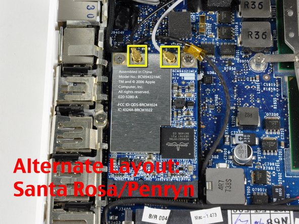
    • Disconnect the three antenna cables from the Airport card on the left side of the computer. Gently pull an antenna cable straight up to remove it.

    • Notice the order of the antenna cables from left to right is black, blue, and gray.

    • If you have a MacBook Core 2 Duo Santa Rosa/Penryn, there are only two antenna cables on the Airport card--black on the left, and gray on the right.

  14. Este passo não foi traduzido. Ajude a traduzi-lo

    : passo 14, imagem 1 %32
    • Remove the following 2 screws from the Airport card:

    • One 3 mm Phillips from the left side.

    • One 8 mm Phillips from the right side.

  15. Este passo não foi traduzido. Ajude a traduzi-lo

    : passo 15, imagem 1 %32
    • Grasp the Airport card at its top and slide it toward the screen and out of the computer.

Linha de Chegada

86 outras pessoas executaram este guia.

iRobot

Membro desde: 09/24/09

1 Reputação

Autoria de 636 guias

2 comentários

This guide was great but I have the new Unibody MacBook Pro 13-inch, 2.26GHz. Does anyone know how to replace the wireless card in this new type of MacBook? Thanks!

James McGrath - Responder

Very good article, I understand and receive more things, waiting for many more articles to come from you. thank you very much quordle

ledonna - Responder

Adicione um comentário

Exibir estatísticas:

Últimas 24 horas: 2

Últimos 7 dias: 21

Últimos 30 dias: 83

Duração total: 144,989