Esta versão pode conter edições incorretas. Mude para o último instantâneo verificado.
O que você precisa
-
-
Com uma chave Pentalobe P5, remova dez parafusos que fixam a estrutura inferior, com os seguintes comprimentos:
-
Dois parafusos de 9 mm
-
Oito parafusos de 2,6 mm
-
-
-
Pegue a aba de plástico transparente presa ao conector da bateria e puxe-a paralelamente à placa, em direção à borda da frente do Air.
-
-
Este passo não foi traduzido. Ajude a traduzi-lo
-
Use the flat end of a spudger to pry the I/O board cable connector up out of its socket on the I/O board.
-
-
Este passo não foi traduzido. Ajude a traduzi-lo
-
Carefully peel the I/O board cable from the adhesive securing it to the top of the fan.
-
-
Este passo não foi traduzido. Ajude a traduzi-lo
-
While gently pulling the I/O board cable upward near its connection to the logic board, use the flat end of a spudger to pry up on alternating sides of the connector to help "walk" it out of its socket.
-
Remove the I/O board cable.
-
-
Este passo não foi traduzido. Ajude a traduzi-lo
-
Use the tip of a spudger to carefully flip up the retaining flap on the fan cable ZIF socket.
-
-
Este passo não foi traduzido. Ajude a traduzi-lo
-
Peel the rubber gasket off the adhesive on the top of the fan.
-
-
Este passo não foi traduzido. Ajude a traduzi-lo
-
Remove the following three screws securing the fan to the upper case:
-
One 3.6 mm T5 Torx screw
-
One 2.7 mm T5 Torx screw
-
One 3.6 mm T5 Torx screw with a short head
-
-
Este passo não foi traduzido. Ajude a traduzi-lo
-
Lift the fan from the I/O board side and pull it free from the upper case.
-
Removing the fan will also disconnect the fan ribbon cable. Be careful not to snag it.
-
-
Este passo não foi traduzido. Ajude a traduzi-lo
-
Disconnect the I/O board by pulling its power cable away from its socket on the logic board.
-
-
Este passo não foi traduzido. Ajude a traduzi-lo
-
Use the flat end of a spudger to pry the left speaker cable connector up and out of its socket on the I/O board.
-
-
Este passo não foi traduzido. Ajude a traduzi-lo
-
Use the tip of a spudger to carefully flip up the retaining flap on the microphone ribbon cable ZIF socket.
-
-
-
Este passo não foi traduzido. Ajude a traduzi-lo
-
Remove the single 3.6 mm T5 Torx screw securing the I/O board to the upper case.
-
-
Este passo não foi traduzido. Ajude a traduzi-lo
-
Gently de-route the camera cable from its notch on the I/O board and push it out of the way with the tip of a spudger.
-
-
Este passo não foi traduzido. Ajude a traduzi-lo
-
Lift the I/O board from the logic board side and pull it free from the upper case.
-
Removing the I/O board will also disconnect the microphone ribbon cable. Be careful not to snag it.
-
-
Este passo não foi traduzido. Ajude a traduzi-lo
-
Remove the following five screws securing the battery to the upper case:
-
Three 6.3 mm T5 Torx screws
-
Two 2.4 mm T5 Torx screws
-
-
Este passo não foi traduzido. Ajude a traduzi-lo
-
Lift the battery from its edge nearest the logic board and remove it from the upper case.
-
-
Este passo não foi traduzido. Ajude a traduzi-lo
-
Grab the plastic pull tab secured to the display data cable lock and rotate it towards the top side of the computer.
-
-
Este passo não foi traduzido. Ajude a traduzi-lo
-
Pull the display data cable connector straight away from its socket.
-
-
Este passo não foi traduzido. Ajude a traduzi-lo
-
Use the flat end of a spudger to pry both antenna cable connectors up and off their sockets on the AirPort/Bluetooth card.
-
-
Este passo não foi traduzido. Ajude a traduzi-lo
-
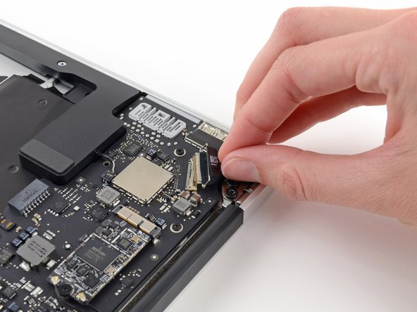
Disconnect the camera cable connector with the tip of a spudger.
-
Pull the camera cable parallel to the face of the I/O board toward the front edge of the Air to disconnect it from its socket.
-
-
Este passo não foi traduzido. Ajude a traduzi-lo
-
Use the tip of a spudger or your fingernail to flip up the retaining flap on the trackpad ribbon cable ZIF socket.
-
Pull the trackpad ribbon cable straight out of its socket toward the front edge of the Air.
-
-
Este passo não foi traduzido. Ajude a traduzi-lo
-
Use the tip of a spudger to flip up the retaining flap on the keyboard backlight ribbon cable ZIF socket.
-
Use your spudger to gently pull the keyboard backlight ribbon cable out of its socket.
-
-
Este passo não foi traduzido. Ajude a traduzi-lo
-
Use the flat end of a spudger to pry the right speaker cable connector up and out of its socket on the logic board.
-
-
Este passo não foi traduzido. Ajude a traduzi-lo
-
Remove the six 6.3 mm T5 Torx screws securing the logic board to the upper case.
-
-
Este passo não foi traduzido. Ajude a traduzi-lo
-
Remove the inner two 4.9 mm T8 Torx screws securing the antenna cable retainer and left clutch hinge to the upper case.
-
-
Este passo não foi traduzido. Ajude a traduzi-lo
-
Push the antenna cable retainer away slightly and remove the 3 mm T5 Torx screw securing the end of the heat sink to the upper case.
-
-
Este passo não foi traduzido. Ajude a traduzi-lo
-
Slide the flat end of a spudger under the right speaker from the end nearest the hinge to the front edge of the Air to loosen the adhesive.
-
Remove the right speaker from the upper case.
-
-
Este passo não foi traduzido. Ajude a traduzi-lo
-
Carefully remove the logic board assembly from the upper case, minding any cables that may get caught.
-
Keep loose cables clear of the board so they aren't caught under it.
-
Make sure the antenna cables are inserted into their respective notches, as highlighted in the second picture.
-
-
Este passo não foi traduzido. Ajude a traduzi-lo
-
Remove the single 2.85 mm T5 Torx screw securing the SSD to the logic board.
-
-
Este passo não foi traduzido. Ajude a traduzi-lo
-
Pull the drive straight out of its socket and remove it from the logic board.
-
-
Este passo não foi traduzido. Ajude a traduzi-lo
-
Remove the single 2.9 mm T5 Torx screw securing the AirPort/Bluetooth board to the logic board.
-
-
Este passo não foi traduzido. Ajude a traduzi-lo
-
Slightly lift the free end of the AirPort/Bluetooth board and pull it out of its socket on the logic board.
-
Remove the AirPort/Bluetooth board from the logic board.
-
-
Este passo não foi traduzido. Ajude a traduzi-lo
-
Remove the four 2.5 mm T5 Torx screws securing the heat sink to the logic board.
-
-
Este passo não foi traduzido. Ajude a traduzi-lo
-
Make sure the antenna cables are inserted into their respective notches on the logic board, as highlighted in the last picture.
-


Cancelar: não concluí este guia.
73 outras pessoas executaram este guia.

18 comentários
great job! thanks a lot
thank you for making it so easy. Great job, you deserve 5 stars *****
Is it possible to swap Macbook air's (2013) logic board for newer model's logic board? (let's say for 2015 macbook air's logic board).