Esta versão pode conter edições incorretas. Mude para o último instantâneo verificado.
O que você precisa
-
-
Com uma chave Pentalobe P5, remova dez parafusos que fixam a estrutura inferior, com os seguintes comprimentos:
-
Dois parafusos de 9 mm
-
Oito parafusos de 2,6 mm
-
-
Este passo não foi traduzido. Ajude a traduzi-lo
-
Grab the clear plastic pull tab attached to the battery connector and pull it toward the front edge of the Air to disconnect the battery from the logic board.
-
-
Este passo não foi traduzido. Ajude a traduzi-lo
-
Use the flat end of a spudger to pry the I/O board cable connector upward out of its socket on the I/O board.
-
-
Este passo não foi traduzido. Ajude a traduzi-lo
-
Carefully peel the I/O board cable from the top of the fan.
-
-
Este passo não foi traduzido. Ajude a traduzi-lo
-
While gently pulling the I/O board cable upward near its connection to the logic board, use the tip of a spudger to pry upward on alternating sides of the connector to help "walk" it out of its socket.
-
Remove the I/O board cable.
-
-
-
Este passo não foi traduzido. Ajude a traduzi-lo
-
Use the tip of a spudger to carefully flip up the retaining flap on the fan cable ZIF socket.
-
-
Este passo não foi traduzido. Ajude a traduzi-lo
-
Peel the rubber gasket off the adhesive on the top of the fan.
-
-
Este passo não foi traduzido. Ajude a traduzi-lo
-
Remove the following three screws securing the fan to the upper case:
-
One 3.6 mm T5 Torx screw
-
One 2.7 mm T5 Torx screw
-
One 3.6 mm T5 Torx screw with a short head
-
-
Este passo não foi traduzido. Ajude a traduzi-lo
-
Lift the fan out of the upper case and carefully pull the fan ribbon cable out of its socket as you remove it from the Air.
-
-
Este passo não foi traduzido. Ajude a traduzi-lo
-
Disconnect the I/O board by pulling the power cable away from its socket on the logic board.
-
-
Este passo não foi traduzido. Ajude a traduzi-lo
-
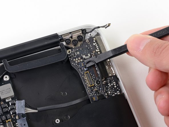
Pull the camera cable parallel to the face of the I/O board toward the hinge of the Air to disconnect it from its socket, using the tip of a spudger to help push the connector out of its socket.
-
-
Este passo não foi traduzido. Ajude a traduzi-lo
-
Use the flat end of a spudger to pry the left speaker cable connector up and out of its socket on the I/O board.
-
-
Este passo não foi traduzido. Ajude a traduzi-lo
-
Use the tip of a spudger to flip up the retaining flap securing the microphone ribbon cable to the I/O board.
-
Use the tip of a spudger to remove the volume button ribbon cable from its ZIF connector on the I/O board.
-
-
Este passo não foi traduzido. Ajude a traduzi-lo
-
Remove the single 4.0 mm T5 Torx screw securing the I/O board to the upper case.
-
-
Este passo não foi traduzido. Ajude a traduzi-lo
-
Carefully lift the I/O board from its edge nearest the logic board and remove it from the upper case.
-


Cancelar: não concluí este guia.
41 outras pessoas executaram este guia.

4 comentários
I bought a used I/O board on ebay for $30. Replacing the i/o board solved my problem with the "fan stack" heat sensor which had been unreadable and causing the computer to run very slowly and the fan to run full speed. It was listed like this:
2012 13" MacBook Air MagSafe II DC audio I/O Power Board A1466
HELP NEEDED PLEASE !
While removing the Board I torn apart the pièce at the end of the cable (linked to side) on the l'est of the lasr image. What is it and Howard Can I remplace it ?
The is a connection that is near the middle outside of the board (near the wifi card) and it looks similar to the I/O connection. Would anyone be able to identify what that connection is and what it is for. I have a 2012 MBA and I wondered if it is a PCIe connection that is unused???