Esta versão pode conter edições incorretas. Mude para o último instantâneo verificado.
O que você precisa
-
-
Remova os dez parafusos a seguir:
-
Dois parafusos Pentalobe de 5 pontas de 9 mm
-
Oito parafusos Pentalobe de 5 pontas de 2,6 mm
-
-
Este passo não foi traduzido. Ajude a traduzi-lo
-
Grab the clear plastic pull tab attached to the battery connector and pull it toward the front edge of the Air to disconnect the battery from the logic board.
-
-
Este passo não foi traduzido. Ajude a traduzi-lo
-
Use the flat end of a spudger to pry the I/O board cable connector upward out of its socket on the I/O board.
-
-
Este passo não foi traduzido. Ajude a traduzi-lo
-
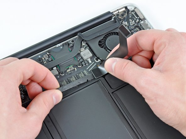
Carefully peel the I/O board cable from the top of the fan.
-
While gently pulling the I/O board cable upward near its connection to the logic board, use the tip of a spudger to pry upward on alternating sides of the connector to help "walk" it out of its socket.
-
Remove the I/O board cable.
-
-
-
Este passo não foi traduzido. Ajude a traduzi-lo
-
Use the tip of a spudger to carefully flip up the retaining flap on the fan cable ZIF socket.
-
-
Este passo não foi traduzido. Ajude a traduzi-lo
-
Peel the rubber gasket off the adhesive on the top of the fan.
-
-
Este passo não foi traduzido. Ajude a traduzi-lo
-
Remove the following three screws securing the fan to the upper case:
-
One 3.6 mm T5 Torx screw
-
One 2.7 mm T5 Torx screw
-
One 3.6 mm T5 Torx screw with a short head
-
-
Este passo não foi traduzido. Ajude a traduzi-lo
-
Lift the fan out of the upper case and carefully pull the fan ribbon cable out of its socket as you remove it from the Air.
-
-
Este passo não foi traduzido. Ajude a traduzi-lo
-
Disconnect the I/O board by pulling the power cable away from its socket on the logic board.
-
-
Este passo não foi traduzido. Ajude a traduzi-lo
-
Pull the camera cable parallel to the face of the I/O board toward the corner of the Air to disconnect it from its socket, using the tip of a spudger to help push the connector out of its socket.
-
-
Este passo não foi traduzido. Ajude a traduzi-lo
-
Use the flat end of a spudger to pry the left speaker cable connector up and out of its socket on the I/O board.
-
De-route the left speaker cable from its retainer on the I/O board.
-
-
Este passo não foi traduzido. Ajude a traduzi-lo
-
Use the flat end of a spudger to pry the microphone cable connector up and out of its socket on the I/O board.
-
-
Este passo não foi traduzido. Ajude a traduzi-lo
-
Remove the single 3.6 mm T5 Torx screw securing the I/O board to the upper case.
When inserting new board, make sure the headphones jack socket rim is registered properly with the case hole before tightening T5 screw.
-
-
Este passo não foi traduzido. Ajude a traduzi-lo
-
Carefully lift the I/O board from its edge nearest the logic board and remove it from the upper case.
-


Cancelar: não concluí este guia.
20 outras pessoas executaram este guia.

3 comentários
Superb instructions - made it easy!
Thanks! It saved me $250 dollars doing this. One thing I want to mention to anyone doing this, be careful with the dis-attachment of some smaller cables. They are very sensitive and have tiny parts sometimes that can come off. Fortunately for me, it didn’t prevent it from working, but just a warning. Notice how you are detaching those little cables very carefully before putting them back. I’m thinking about the microphone cable connector up and out of its socket on the I/O boar specifically.