Esta versão pode conter edições incorretas. Mude para o último instantâneo verificado.
O que você precisa
-
-
Com uma chave Pentalobe P5, remova dez parafusos que fixam a estrutura inferior, com os seguintes comprimentos:
-
Dois parafusos de 9 mm
-
Oito parafusos de 2,6 mm
-
-
-
Pegue a aba de plástico transparente presa ao conector da bateria e puxe-a paralelamente à placa, em direção à borda da frente do Air.
-
-
Este passo não foi traduzido. Ajude a traduzi-lo
-
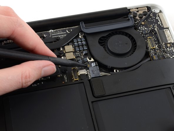
Use the flat end of a spudger to pry the I/O board cable connector up out of its socket on the I/O board.
-
-
Este passo não foi traduzido. Ajude a traduzi-lo
-
Carefully peel the I/O board cable from the adhesive securing it to the top of the fan.
-
-
Este passo não foi traduzido. Ajude a traduzi-lo
-
While gently pulling the I/O board cable upward near its connection to the logic board, use the flat end of a spudger to pry up on alternating sides of the connector to help "walk" it out of its socket.
-
Remove the I/O board cable.
-
-
Este passo não foi traduzido. Ajude a traduzi-lo
-
Use the tip of a spudger to carefully flip up the retaining flap on the fan cable ZIF socket.
-
-
Este passo não foi traduzido. Ajude a traduzi-lo
-
Peel the rubber gasket off the adhesive on the top of the fan.
-
-
Este passo não foi traduzido. Ajude a traduzi-lo
-
Remove the following three screws securing the fan to the upper case:
-
One 5.2 mm T5 Torx screw
-
One 3.3 mm T5 Torx screw
-
One 4.4 mm T5 Torx screw with a short head
-
-
Este passo não foi traduzido. Ajude a traduzi-lo
-
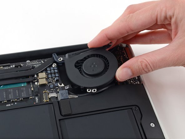
Lift the fan from the I/O board side and pull it free from the upper case.
-
Removing the fan will also disconnect the fan ribbon cable. Be careful not to snag it.
-
-
Este passo não foi traduzido. Ajude a traduzi-lo
-
Disconnect the I/O board by pulling its power cable away from its socket on the logic board.
-
-
Este passo não foi traduzido. Ajude a traduzi-lo
-
Use the flat end of a spudger to pry the left speaker cable connector up and out of its socket on the I/O board.
-
-
Este passo não foi traduzido. Ajude a traduzi-lo
-
Use the tip of a spudger to carefully flip up the retaining flap on the microphone ribbon cable ZIF socket.
-
-
-
Este passo não foi traduzido. Ajude a traduzi-lo
-
Remove the single 4.1 mm T5 Torx screw securing the I/O board to the upper case.
-
-
Este passo não foi traduzido. Ajude a traduzi-lo
-
Gently de-route the camera cable from its notch on the I/O board and push it out of the way with the tip of a spudger.
-
-
Este passo não foi traduzido. Ajude a traduzi-lo
-
Lift the I/O board from the logic board side and pull it free from the upper case.
-
Removing the I/O board will also disconnect the microphone ribbon cable. Be careful not to snag it.
-
-
-
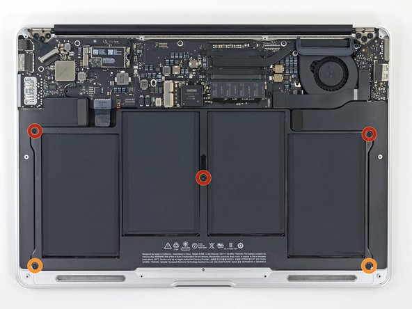
Remova os cinco parafusos a seguir que fixam a bateria à estrutura superior:
-
Três parafusos Torx T5 de 6,9 mm
-
Dois parafusos Torx T5 de 3,0 mm
-
-
-
Levante a bateria pela borda mais próxima da placa lógica e remova-a da estrutura superior.
-
Carregue até 100% e continue carregando por ao menos mais duas horas. Em seguida, tire o plugue da tomada e use normalmente até descarregar a bateria. Quando vir o aviso de bateria fraca, salve seu trabalho e deixe o laptop ligado até entrar em modo repouso por bateria fraca. Aguarde 5 horas ou mais e carregue o laptop ininterruptamente até 100%.
-
Se você notar algum comportamento incomum ou problemas após a instalação da nova bateria, talvez seja necessário resetar o SMC do MacBook.
-
-
Este passo não foi traduzido. Ajude a traduzi-lo
-
Grab the plastic pull tab secured to the display data cable lock and rotate it towards the top side of the computer.
-
-
Este passo não foi traduzido. Ajude a traduzi-lo
-
Pull the display data cable connector straight away from its socket.
-
-
Este passo não foi traduzido. Ajude a traduzi-lo
-
Use the flat end of a spudger to pry both antenna cable connectors up and off their sockets on the AirPort/Bluetooth card.
-
-
Este passo não foi traduzido. Ajude a traduzi-lo
-
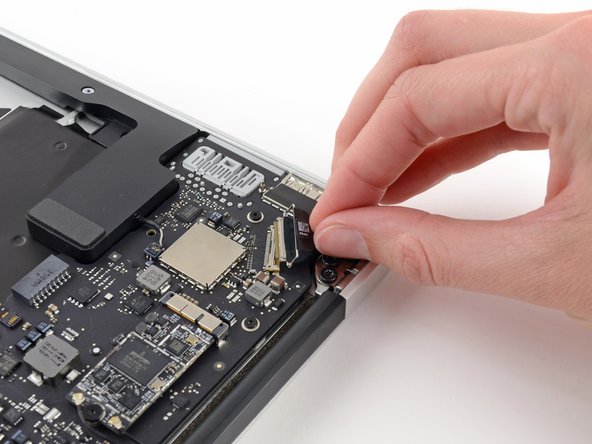
Disconnect the camera cable connector with the tip of a spudger.
-
Pull the camera cable parallel to the face of the I/O board toward the front edge of the Air to disconnect it from its socket.
-
-
Este passo não foi traduzido. Ajude a traduzi-lo
-
Use the tip of a spudger or your fingernail to flip up the retaining flap on the trackpad ribbon cable ZIF socket.
-
Pull the trackpad ribbon cable straight out of its socket toward the front edge of the Air.
-
-
Este passo não foi traduzido. Ajude a traduzi-lo
-
Use the tip of a spudger to flip up the retaining flap on the keyboard backlight ribbon cable ZIF socket.
-
Use your spudger to gently pull the keyboard backlight ribbon cable out of its socket.
-
-
Este passo não foi traduzido. Ajude a traduzi-lo
-
Use the flat end of a spudger to pry the right speaker cable connector up and out of its socket on the logic board.
-
-
Este passo não foi traduzido. Ajude a traduzi-lo
-
Remove the six 6.3 mm T5 Torx screws securing the logic board to the upper case.
-
-
Este passo não foi traduzido. Ajude a traduzi-lo
-
Remove the inner two 4.9 mm T8 Torx screws securing the antenna cable retainer and left clutch hinge to the upper case.
-
-
Este passo não foi traduzido. Ajude a traduzi-lo
-
Push the antenna cable retainer away slightly and remove the 3 mm T5 Torx screw securing the end of the heat sink to the upper case.
-
-
Este passo não foi traduzido. Ajude a traduzi-lo
-
Slide the flat end of a spudger under the right speaker from the end nearest the hinge to the front edge of the Air to loosen the adhesive.
-
Remove the right speaker from the upper case.
-
-
Este passo não foi traduzido. Ajude a traduzi-lo
-
Carefully remove the logic board assembly from the upper case, minding any cables that may get caught.
-
Keep loose cables clear of the board so they aren't caught under it.
-
Make sure the antenna cables are inserted into their respective notches, as highlighted in the second picture.
-
-
Este passo não foi traduzido. Ajude a traduzi-lo
-
Remove the single 2.85 mm T5 Torx screw securing the SSD to the logic board.
-
-
Este passo não foi traduzido. Ajude a traduzi-lo
-
Pull the drive straight out of its socket and remove it from the logic board.
-
-
Este passo não foi traduzido. Ajude a traduzi-lo
-
Remove the single 2.9 mm T5 Torx screw securing the AirPort/Bluetooth board to the logic board.
-
-
Este passo não foi traduzido. Ajude a traduzi-lo
-
Slightly lift the free end of the AirPort/Bluetooth board and pull it out of its socket on the logic board.
-
Remove the AirPort/Bluetooth board from the logic board.
-
-
Este passo não foi traduzido. Ajude a traduzi-lo
-
Remove the four 2.5 mm T5 Torx screws securing the heat sink to the logic board.
-
-
Este passo não foi traduzido. Ajude a traduzi-lo
-
Make sure the antenna cables are inserted into their respective notches on the logic board, as highlighted in the last picture.
-


Cancelar: não concluí este guia.
78 outras pessoas executaram este guia.


15 comentários
Wow, you saved me $1000 bucks! I spilled brandy on my MacBook Air and followed your instructions to completely strip it down. I followed instructions for cleaning circuit boards after a spill from another page on this site. My MacBook works perfectly now!
Your instructions were great. You might note that there is some variation in the placement of different components, ribbon connectors, etc., but I figured it out by zooming in on your pictures and finding a picture of each exact component. They look the same, even though they are in different spots. I found out you can dunk the circuit boards in 91% rubbing alcohol, clean the parts with a soft toothbrush, and let it all dry. I didn’t bother with removing and replacing the heat sink and thermal paste. After soaking in the alcohol, I saw that the heat sinks were still firmly attached thermal paste looked fine, so I left it alone. I liked your specific descriptions about which way to pull or lift the ribbon connectors, and using the right tools! Thanks!
I am afraid if you soaked the whole unit in alcohol, the heat sink paste is probably ruined? If the unit seems to get hot or shut off spontaneously, I would consider taking it apart AGAIN, and cleaning and relating the heat sink with fresh new thermal paste. You can clean the old paste off with Alcohol, do you see why that worries me ;~)
Can anyone please let me know where to buy Motherboard, my macbook air is not getting started. they said there is a moisture on the logic board.
Hi Sriram, we have links to the motherboards (Apple calls them Logic Boards) at the top of this guide.