Esta versão pode conter edições incorretas. Mude para o último instantâneo verificado.
O que você precisa
-
-
Com uma chave Pentalobe P5, remova dez parafusos que fixam a estrutura inferior, com os seguintes comprimentos:
-
Dois parafusos de 9 mm
-
Oito parafusos de 2,6 mm
-
-
-
Pegue a aba de plástico transparente presa ao conector da bateria e puxe-a paralelamente à placa, em direção à borda da frente do Air.
-
-
Este passo não foi traduzido. Ajude a traduzi-lo
-
Use the flat end of a spudger to pry the I/O board cable connector up out of its socket on the I/O board.
-
-
Este passo não foi traduzido. Ajude a traduzi-lo
-
Carefully peel the I/O board cable from the adhesive securing it to the top of the fan.
-
-
Este passo não foi traduzido. Ajude a traduzi-lo
-
While gently pulling the I/O board cable upward near its connection to the logic board, use the flat end of a spudger to pry up on alternating sides of the connector to help "walk" it out of its socket.
-
Remove the I/O board cable.
-
-
Este passo não foi traduzido. Ajude a traduzi-lo
-
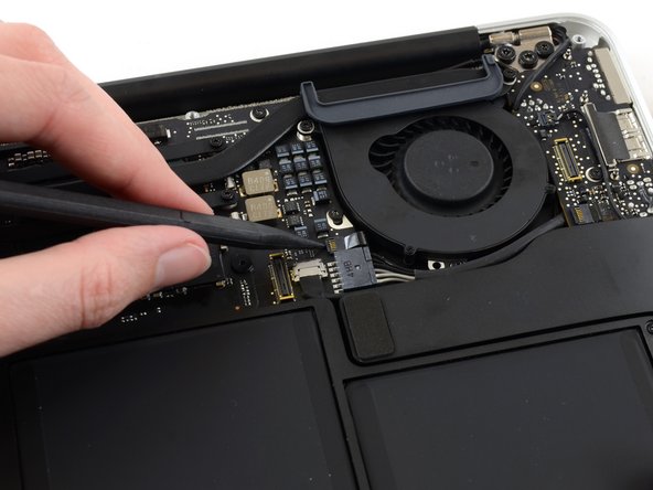
Use the tip of a spudger to carefully flip up the retaining flap on the fan cable ZIF socket.
-
-
Este passo não foi traduzido. Ajude a traduzi-lo
-
Peel the rubber gasket off the adhesive on the top of the fan.
-
-
Este passo não foi traduzido. Ajude a traduzi-lo
-
Remove the following three screws securing the fan to the upper case:
-
One 5.2 mm T5 Torx screw
-
One 3.3 mm T5 Torx screw
-
One 4.4 mm T5 Torx screw with a short head
-
-
-
Este passo não foi traduzido. Ajude a traduzi-lo
-
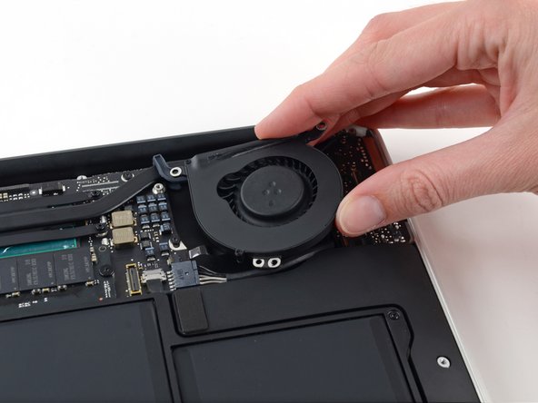
Lift the fan from the I/O board side and pull it free from the upper case.
-
Removing the fan will also disconnect the fan ribbon cable. Be careful not to snag it.
-
-
Este passo não foi traduzido. Ajude a traduzi-lo
-
Disconnect the I/O board by pulling its power cable away from its socket on the logic board.
-
-
Este passo não foi traduzido. Ajude a traduzi-lo
-
Use the flat end of a spudger to pry the left speaker cable connector up and out of its socket on the I/O board.
-
-
Este passo não foi traduzido. Ajude a traduzi-lo
-
Use the tip of a spudger to carefully flip up the retaining flap on the microphone ribbon cable ZIF socket.
-
-
Este passo não foi traduzido. Ajude a traduzi-lo
-
Remove the single 4.1 mm T5 Torx screw securing the I/O board to the upper case.
-
-
Este passo não foi traduzido. Ajude a traduzi-lo
-
Gently de-route the camera cable from its notch on the I/O board and push it out of the way with the tip of a spudger.
-
-
Este passo não foi traduzido. Ajude a traduzi-lo
-
Lift the I/O board from the logic board side and pull it free from the upper case.
-
Removing the I/O board will also disconnect the microphone ribbon cable. Be careful not to snag it.
-
-
Este passo não foi traduzido. Ajude a traduzi-lo
-
Use the flat end of a spudger to pry each of the antenna connectors up from their sockets on the AirPort/Bluetooth card.
-
-
Este passo não foi traduzido. Ajude a traduzi-lo
-
Disconnect the camera cable connector with the tip of a spudger.
-
Pull the camera cable parallel to the face of the I/O board toward the front edge of the Air to disconnect it from its socket.
-
-
Este passo não foi traduzido. Ajude a traduzi-lo
-
Pull the plastic tab on the display data cable connector to unlock it.
-
-
Este passo não foi traduzido. Ajude a traduzi-lo
-
Pull the display data cable connector straight out of its socket.
-
-
Este passo não foi traduzido. Ajude a traduzi-lo
-
Remove the inner four (two on each side) 5.6 mm T8 Torx screws securing the right and left display hinges to the upper case.
-
-
Este passo não foi traduzido. Ajude a traduzi-lo
-
Gently de-route the antenna cables out of the channel cut into the upper case.
-
-
Este passo não foi traduzido. Ajude a traduzi-lo
-
While holding the Air steady, remove the remaining 5.6 mm T8 Torx screw from the left display bracket.
-
-
Este passo não foi traduzido. Ajude a traduzi-lo
-
Remove the last 5.6 mm T8 Torx screw securing the display to the upper case.
-
-
Este passo não foi traduzido. Ajude a traduzi-lo
-
Open the Air slightly to allow room for the hinges to slide out of their notches.
-
Push the upper case slightly toward the display assembly, then push it back from the hinges.
-
Once the two display hinges have cleared the upper case, remove the display and set it aside.
-


Cancelar: não concluí este guia.
116 outras pessoas executaram este guia.

34 comentários
Followed this guide to replace a broken display assembly on my Macbook Air. Complete everything in 40 minutes with little problem. My only problem was ripping the tab off the microphone ribbon cable which made this part a little bit more difficult, but didn't end up being a huge deal.
Would you be able to replace the screen with a 13" macbook pro retina screen on the newest 2015 13" Macbook Air?
Not even close.
For people who need context with their answers rather than just receiving an ambiguous NO:
The screens from the MacBook Air models and the regular MacBook & MacBook Pro are NOT INTERCHANGEABLE BECAUSE:
they have different connectors. The air has 13 pins and the MacBooks have 20 pins.
(I think that is correct, might be 21 pins)
there is no realistic way to alter the hardware of device.
You would have to use some ritual magic and tweaker math.
We are talking about swapping different architectures in this scenario, so beyond that maybe there is a bridging connector but I would imagine that you would have to install some kind of accelerator to compensate for the difference and render the display properly.
However, on a lighter note:
•2010-2017 Airs have compatible LCDs 11 and 13 inch can be swapped for testing purposes.
•2013-2017 Airs are fully compatible.
•2010-2011 11" Airs have a shorter WIFI cable. •2012 is usable on 2010-2012.
LD GROUP -