Esta versão pode conter edições incorretas. Mude para o último instantâneo verificado.
O que você precisa
-
Este passo não foi traduzido. Ajude a traduzi-lo
-
Remove the following ten screws:
-
Two 8 mm 5-point Pentalobe screws
-
Eight 2.5 mm 5-point Pentalobe screws
-
-
Este passo não foi traduzido. Ajude a traduzi-lo
-
Wedge your fingers between the display and the lower case and pull upward to pop the lower case off the Air.
-
-
Este passo não foi traduzido. Ajude a traduzi-lo
-
Use the flat end of a spudger to pry both short sides of the battery connector upward to disconnect it from its socket on the logic board.
-
Bend the battery cable slightly away from the logic board so the connector will not accidentally contact its socket.
-
-
Este passo não foi traduzido. Ajude a traduzi-lo
-
Remove the single 2.9 mm T5 Torx screw securing the SSD to the logic board.
-
-
Este passo não foi traduzido. Ajude a traduzi-lo
-
Use a spudger to help lift the free end of the SSD just enough to grab it with your other hand.
-
Pull the drive straight out of its socket and remove it from the logic board.
-
-
Este passo não foi traduzido. Ajude a traduzi-lo
-
Use the flat end of a spudger to pry the I/O board cable up from its socket on the I/O board.
-
-
Este passo não foi traduzido. Ajude a traduzi-lo
-
Peel the I/O board cable up from the adhesive securing it to the fan.
-
-
-
Este passo não foi traduzido. Ajude a traduzi-lo
-
Use the flat end of a spudger to lift the I/O board connector up and out of its socket on the logic board
-
Remove the I/O board cable.
-
-
Este passo não foi traduzido. Ajude a traduzi-lo
-
Use the tip of a spudger to carefully flip up the retaining flap on the fan cable ZIF socket.
-
-
Este passo não foi traduzido. Ajude a traduzi-lo
-
Remove the following three screws securing the fan to the upper case:
-
Two 5.2 mm T5 Torx screws
-
One 3.6 mm T5 Torx screw
-
-
Este passo não foi traduzido. Ajude a traduzi-lo
-
Lift the fan out of the upper case and carefully pull the fan ribbon cable out of its socket as you remove it from the Air.
-
-
Este passo não foi traduzido. Ajude a traduzi-lo
-
Remove the following five screws securing the battery to the upper case:
-
Two 5.2 mm T5 Torx screws
-
One 6 mm T5 Torx screw
-
Two 2.6 mm T5 Torx screws
-
-
Este passo não foi traduzido. Ajude a traduzi-lo
-
Lift the battery from its edge nearest the logic board and remove it from the upper case.
-
-
Este passo não foi traduzido. Ajude a traduzi-lo
-
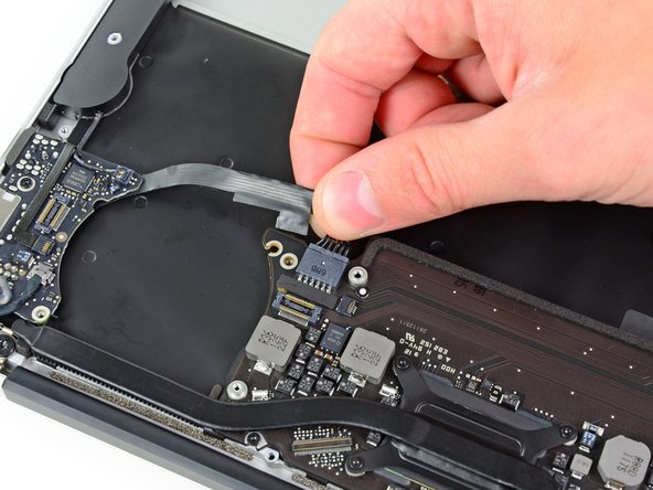
Disconnect the I/O board by pulling the power cable away from its socket on the logic board.
-
-
Este passo não foi traduzido. Ajude a traduzi-lo
-
Use the tip of a spudger to carefully flip up the retaining flap on the microphone cable ZIF socket.
-
Pull the microphone ribbon cable straight out of its socket.
-
-
Este passo não foi traduzido. Ajude a traduzi-lo
-
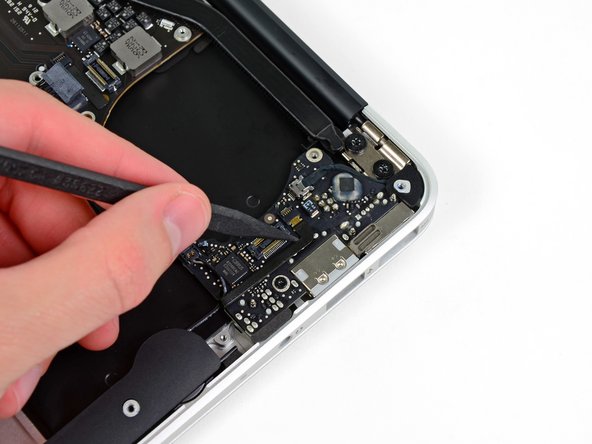
Use the flat end of a spudger to pry the left speaker cable connector up and out of its socket on the I/O board.
-
-
Este passo não foi traduzido. Ajude a traduzi-lo
-
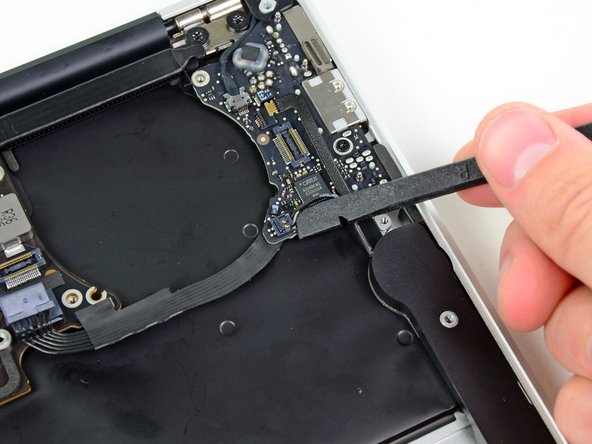
Pull the camera cable parallel to the face of the I/O board toward the rear edge of the Air to disconnect it from its socket.
-
-
Este passo não foi traduzido. Ajude a traduzi-lo
-
Remove the small rubber gasket from the corner of the upper case nearest the I/O board.
-
-
Este passo não foi traduzido. Ajude a traduzi-lo
-
Remove the single 3.6 mm T5 Torx screw securing the I/O board to the upper case.
-
-
Este passo não foi traduzido. Ajude a traduzi-lo
-
Carefully lift the I/O board from its edge nearest the logic board and remove it from the upper case.
-


Cancelar: não concluí este guia.
42 outras pessoas executaram este guia.

5 comentários
Thanks. Great instructions!
Thank you so much. Just replaced my IO board and the whole process went without a hitch. I’m absolutely thrilled now that I can charge my Air without going through an extensive wriggling routine with the MagSafe connector every time.
Good day! As I can see it’s all the same with Air 2012 logic board…
I’m looking the board to replace my 2GB mid 2011, can I take 4GB mid 2012 with 1.7Ghz ..?
This was exactly what I needed!!! I replaced the I/O board and I/O board cable on a macbook 11” A1465 that was not charging or playing sound. It now works. Great explanations and details.
Thanks. Good instructions.