Esta versão pode conter edições incorretas. Mude para o último instantâneo verificado.
O que você precisa
-
Este passo não foi traduzido. Ajude a traduzi-lo
-
Disconnect the I/O board by pulling the power cable away from its socket on the logic board.
-
-
Este passo não foi traduzido. Ajude a traduzi-lo
-
Use the tip of a spudger or your fingernail to flip up the retaining flap on the trackpad ribbon cable ZIF socket.
-
Pull the trackpad ribbon cable straight out of its socket toward the front edge of the Air.
-
-
Este passo não foi traduzido. Ajude a traduzi-lo
-
Use the tip of a spudger to de-route the right speaker cable from the slot cut into the logic board.
-
-
Este passo não foi traduzido. Ajude a traduzi-lo
-
Use the flat end of a spudger to pry the right speaker cable connector up and out of its socket on the logic board.
-
-
-
Este passo não foi traduzido. Ajude a traduzi-lo
-
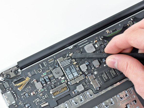
Gently push the tip of a spudger under the black plastic flap stuck to the display data cable lock to make the lock pop upward and away from the socket.
-
While holding the lock away from the socket, use the tip of a spudger and your fingers to gently remove the display data cable from its socket.
-
-
Este passo não foi traduzido. Ajude a traduzi-lo
-
Remove the small rubber gasket from the corner of the upper case near the display data cable.
-
-
Este passo não foi traduzido. Ajude a traduzi-lo
-
Use the flat end of a spudger to pry both antenna cable connectors up and off their sockets on the AirPort/Bluetooth card.
-
-
Este passo não foi traduzido. Ajude a traduzi-lo
-
Gently de-route the antenna cables from the slot cut into the logic board.
-
-
Este passo não foi traduzido. Ajude a traduzi-lo
-
Remove the three 3.6 mm T5 Torx screws securing the logic board to the upper case.
-
-
Este passo não foi traduzido. Ajude a traduzi-lo
-
Gently lift the logic board assembly out of the upper case, minding the fragile heat sink and any cables that may get caught.
-