Esta versão pode conter edições incorretas. Mude para o último instantâneo verificado.
O que você precisa
-
Este passo não foi traduzido. Ajude a traduzi-lo
-
Remove the following ten screws:
-
Two 8 mm 5-point Pentalobe screws
-
Eight 2.5 mm 5-point Pentalobe screws
-
-
Este passo não foi traduzido. Ajude a traduzi-lo
-
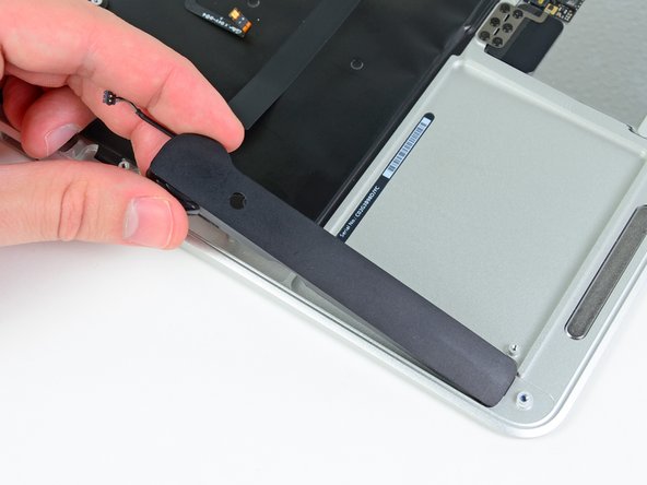
Wedge your fingers between the display and the lower case and pull upward to pop the lower case off the Air.
-
-
Este passo não foi traduzido. Ajude a traduzi-lo
-
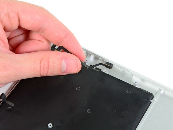
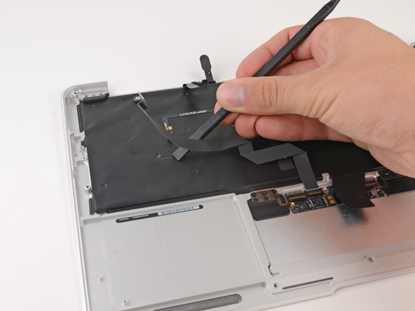
Use the flat end of a spudger to pry both short sides of the battery connector upward to disconnect it from its socket on the logic board.
-
Bend the battery cable slightly away from the logic board so the connector will not accidentally bend back and make contact with its socket.
-
-
Este passo não foi traduzido. Ajude a traduzi-lo
-
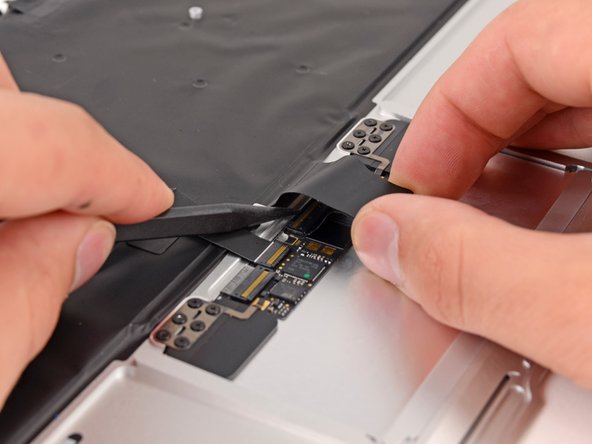
Use the flat end of a spudger to pry the left and right I/O board cable connectors up off their respective sockets on the I/O board.
-
-
Este passo não foi traduzido. Ajude a traduzi-lo
-
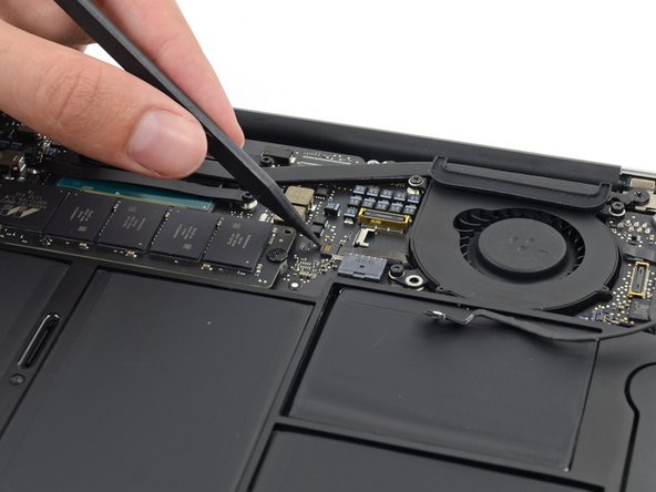
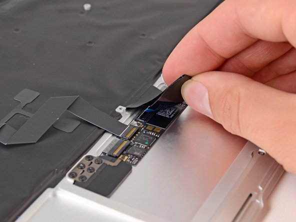
Use the tip of a spudger to carefully push on each side of the iSight camera cable connector to loosen it out of its socket on the logic board.
-
-
Este passo não foi traduzido. Ajude a traduzi-lo
-
Peel the iSight camera cable up off the adhesive securing it to the fan.
-
-
Este passo não foi traduzido. Ajude a traduzi-lo
-
Use the tip of a spudger to carefully flip up the retaining flap on the fan cable ZIF socket.
-
-
Este passo não foi traduzido. Ajude a traduzi-lo
-
Remove the following three screws securing the fan to the upper case:
-
Two 5.5 mm T5 Torx screws
-
One 4.6 mm T5 Torx screw
-
-
Este passo não foi traduzido. Ajude a traduzi-lo
-
Lift, but do not remove the fan out of its recess in the upper case.
-
Carefully pull the fan ribbon cable out of its socket as you remove the fan from the Air.
-
-
Este passo não foi traduzido. Ajude a traduzi-lo
-
Use the flat end of a spudger to pry both antenna connectors up from their sockets on the AirPort/Bluetooth card, and move them out of the way.
-
-
Este passo não foi traduzido. Ajude a traduzi-lo
-
Remove the following five screws securing the battery to the upper case:
-
Two 5.2 mm T5 Torx screws
-
One 6 mm T5 Torx screw
-
Two 2.6 mm T5 Torx screws
-
-
Este passo não foi traduzido. Ajude a traduzi-lo
-
Lift the battery from its edge nearest the logic board and remove it from the upper case.
-
-
Este passo não foi traduzido. Ajude a traduzi-lo
-
Disconnect the I/O board by pulling the power cable away from its socket on the logic board.
-
-
-
Este passo não foi traduzido. Ajude a traduzi-lo
-
Use the tip of a spudger to de-route the antenna cables from their notches in the logic board.
-
-
Este passo não foi traduzido. Ajude a traduzi-lo
-
Gently push the tip of a spudger under the black plastic flap stuck to the display data cable lock to make the lock pop upward and away from the socket.
-
While holding the lock away from the socket, gently pull the display data cable out of its socket.
-
-
Este passo não foi traduzido. Ajude a traduzi-lo
-
Use the tip of a spudger to pry under the speaker cable connector, lifting it straight up from its socket.
-
De-route the cable from its notch in the logic board.
-
-
Este passo não foi traduzido. Ajude a traduzi-lo
-
Use the tip of a spudger or your fingernail to flip up the retaining flap on the trackpad ribbon cable ZIF socket.
-
Pull the trackpad ribbon cable straight out of its socket toward the front edge of the Air.
-
-
Este passo não foi traduzido. Ajude a traduzi-lo
-
Use the tip of a spudger to flip up the retaining flap on the keyboard backlight ribbon cable ZIF socket.
-
Pull the keyboard backlight ribbon cable out of its socket.
-
-
Este passo não foi traduzido. Ajude a traduzi-lo
-
Remove the single 2.9 mm T5 Torx screw securing the AirPort/Bluetooth card to the logic board.
-
-
Este passo não foi traduzido. Ajude a traduzi-lo
-
Slightly lift the free end of the AirPort/Bluetooth board and pull it out of its socket on the logic board.
-
-
Este passo não foi traduzido. Ajude a traduzi-lo
-
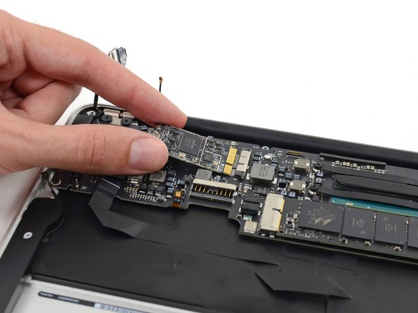
Remove the three 3.6 mm T5 Torx screws securing the logic board to the upper case.
-
In some models these are 3.1 mm T5 Torx screws.
-
-
Este passo não foi traduzido. Ajude a traduzi-lo
-
Gently lift the logic board assembly from the heat sink end and pull it away from the port side of the case to remove it from the Air.
-
-
Este passo não foi traduzido. Ajude a traduzi-lo
-
Remove the small rubber gasket from the corner of the upper case nearest the the I/O board.
-
Remove the gasket from the corner nearest display cable connector.
-
-
Este passo não foi traduzido. Ajude a traduzi-lo
-
Use the tip of a spudger to carefully flip up the retaining flap on the microphone cable ZIF socket.
-
With a pair of tweezers, pull the microphone ribbon cable straight out of its socket.
-
-
Este passo não foi traduzido. Ajude a traduzi-lo
-
Use the tip of a spudger to pry under the speaker cable near the connector, lifting it straight up from its socket.
-
De-route the cable from its notch in the logic board.
-
-
Este passo não foi traduzido. Ajude a traduzi-lo
-
Remove the single 3.6 mm T5 Torx screw securing the I/O board to the upper case.
-
-
Este passo não foi traduzido. Ajude a traduzi-lo
-
Carefully lift the I/O board by its power cable and pull it away from the edge of the case.
-
-
Este passo não foi traduzido. Ajude a traduzi-lo
-
Peel up the six cable loops securing the antenna cables to the upper case.
-
Gently pull the cable loops slightly out of the channel cut into the upper case one at a time.
-
Use your spudger to open up the plastic loops as you de-route the antenna cables through them.
-
-
Este passo não foi traduzido. Ajude a traduzi-lo
-
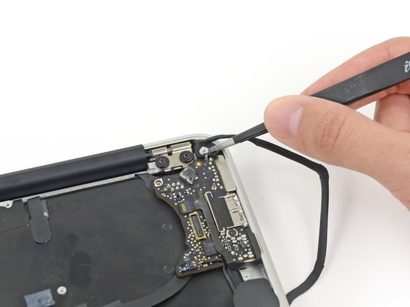
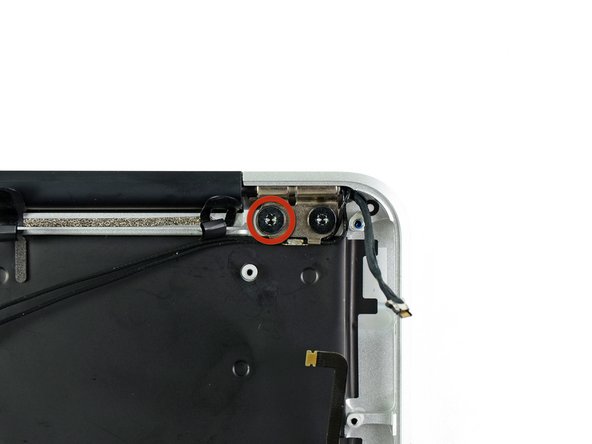
Remove the inner 4.9 mm T8 Torx screw securing each display hinge to the upper case (two screws total).
-
-
Este passo não foi traduzido. Ajude a traduzi-lo
-
While holding the Air steady, remove the remaining 4.9 mm T8 Torx screw from the lower display bracket.
-
-
Este passo não foi traduzido. Ajude a traduzi-lo
-
Remove the last 4.9 mm T8 Torx screw securing the display to the upper case.
-
-
Este passo não foi traduzido. Ajude a traduzi-lo
-
Push the upper case slightly toward the display assembly, then rotate it away from the front of the display assembly.
-
Once the two display hinges have cleared the upper case, remove the display.
-
-
Este passo não foi traduzido. Ajude a traduzi-lo
-
Use the flat end of a spudger to pry the right speaker off the adhesive securing it to the upper case.
-
Remove the right speaker from the upper case.
-
-
Este passo não foi traduzido. Ajude a traduzi-lo
-
Use the flat end of a spudger to pry the left speaker off the adhesive securing it to the upper case.
-
Remove the left speaker from the upper case.
-
-
Este passo não foi traduzido. Ajude a traduzi-lo
-
Use the tip of a spudger to pry the microphone away from the side of the upper case.
-
Remove the microphone from the upper case.
-
Upper case remains.
-
-
Este passo não foi traduzido. Ajude a traduzi-lo
-
Push/lift the keyboard ribbon cable off of the upper case with one hand.
-
With the other hand, use a spudger to flip up the retaining flap on the ZIF connector.
-
Once the retaining flap has been flipped up, carefully pull the ribbon cable straight out of its socket.
-
-
Este passo não foi traduzido. Ajude a traduzi-lo
-
Use the flat end of a spudger to separate the trackpad ribbon cable from the underside of the keyboard.
-
-
Este passo não foi traduzido. Ajude a traduzi-lo
-
Remove the six 1.5 mm Phillips #00 screws securing the trackpad to the upper case.
-
Check your replacement upper case—if it doesn't have this wide T5 screw, remove it to transfer into the replacement.
-
-
Este passo não foi traduzido. Ajude a traduzi-lo
-
Holding the upper case up off the table with one hand, gently push the trackpad up through the upper case.
-
Remove the trackpad from the upper case.
-


Cancelar: não concluí este guia.
15 outras pessoas executaram este guia.


5 comentários
Thanks to Sam Lionheart for this guide! Yes difficult but a great step by step guide!
A member of our family had a coffee spill on their MacBook Air 11". The Apple Store said the machine was "dead" forever and encouraged us to buy new. I used this guide to take the Air apart, clean it, and put it back together. The Air is now working, it has some minor glitches so we will have to watch it and keep the data backed-up. But it works.
The hardest parts, where I wished there was more hints - helps, were putting the Air back together at: #38 reattaching the larger ZIF connector and #15 reattaching the antenna cables.
Thanks to this guide, it was easy. Took me about 2.5 hours total, no problems after re-assembly.
Check your replacement part, mine included cable loops and microphone already installed, so I did not need to remove during disassembly.
Thanks Sam & ifixit!!
Used this guide to replace the keyboard and backlight to my MacBook Air 11” early 2014 A1465! Had to accompany the repair with a few videos on YouTube for help with KB removal and reinstall. Apple charges 231 including labor and iFixit charges $220 for the top cover, but it’s not necessary. Ordered the KB, backlight, and extra set of screws (for the KB) on EBay for about $25 total Installing the 50+ KB screws was very tedious and routing the antenna was a pain, but worth saving $200!
Very good guide. I discovered some a missing screw and gasket. Steps are accurate although I did it in a different order.
My 5 year old spilled a glass of water on the keyboard and after opening and putting the computer upside down for a couple of days, it would not do anything. After sitting dead for a month I decided to crack it open. I found a bunch of corrosion (no surprise) on the logic board and some of the connectors and cleaned it all with alcohol. When I put everything back together, the computer actually began charging and was awakened from its sleeping state. However, the keyboard was not working properly, so I decided to order this upper case. While tedious, the replacement was not too difficult. When I finished and powered on, it started up no problem, but it would not connect to the internet (wifi connected, just no internet). A simple restart fixed this issue. Now, the only issue I’m dealing with is that the left “shift,” “opt/alt,” and '“ctrl” keys do not work. The standard advice is to reset the SMC, but this requires the use of the affected keys. Please help!