Esta versão pode conter edições incorretas. Mude para o último instantâneo verificado.
O que você precisa
-
Este passo não foi traduzido. Ajude a traduzi-lo
-
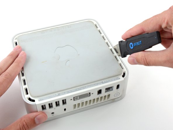
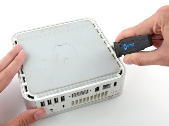
Power down your Mac mini, disconnect all of the cables, and flip it over.
-
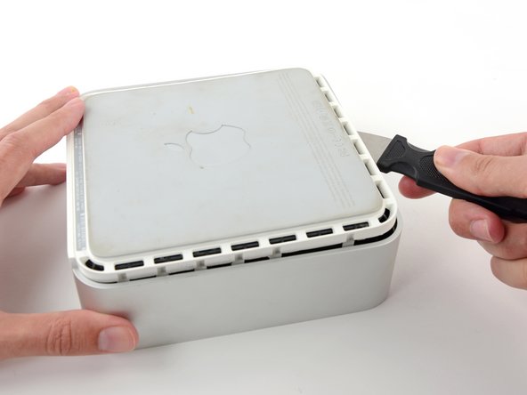
Insert the Jimmy into the crack between the aluminum top housing and the plastic lower housing.
-
The Jimmy should reach a stop about 3/8" down.
-
-
Este passo não foi traduzido. Ajude a traduzi-lo
-
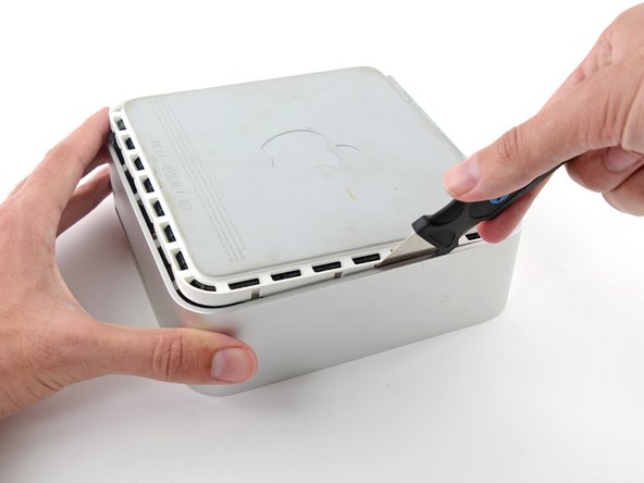
Gently bend the Jimmy outwards to pry the crack open a little larger and lift the lower housing up a small amount.
-
-
Este passo não foi traduzido. Ajude a traduzi-lo
-
Once you have the first side free, rotate the Mac mini and start prying up on the front edge.
-
Use the same prying motion to both bend the clips inward and lift the lower housing up out of the top housing.
-
-
Este passo não foi traduzido. Ajude a traduzi-lo
-
You may need to move the Jimmy along the edge to pry up all of the clips. Be patient and do a little bit at a time.
-
-
Este passo não foi traduzido. Ajude a traduzi-lo
-
Keep working around the perimeter, freeing the clips along the final edge.
-
-
Este passo não foi traduzido. Ajude a traduzi-lo
-
Flip the Mac mini back over and lift the top housing off of the lower housing.
-
-
-
Este passo não foi traduzido. Ajude a traduzi-lo
-
We will first remove the AirPort antenna, located in the lower left corner of this picture.
-
-
Este passo não foi traduzido. Ajude a traduzi-lo
-
Slightly squeeze the two retaining arms toward each other and lift the AirPort antenna off its post.
-
-
Este passo não foi traduzido. Ajude a traduzi-lo
-
Grab the Bluetooth antenna nearest the port side of the computer by the edges of the board and pull it straight up off the internal frame.
-
-
Este passo não foi traduzido. Ajude a traduzi-lo
-
Remove the antenna board near the front of the mini by pulling it straight up off the internal frame.
-
If necessary, remove the piece of tape securing the antenna leads to the internal frame.
-
-
Este passo não foi traduzido. Ajude a traduzi-lo
-
Use the flat end of a spudger to pry the audio ribbon cable connector up off the audio board.
-
-
Este passo não foi traduzido. Ajude a traduzi-lo
-
Remove the following four screws securing the internal frame to the bottom housing:
-
Three 6.7 mm Phillips #00 screws
-
One 9.5 mm Phillips #00 screw
-
-
Este passo não foi traduzido. Ajude a traduzi-lo
-
Lift the internal frame off the bottom housing, starting at the rear edge, until you feel the concealed edge connector on the motherboard disconnect. Then lift straight off, minding the bluetooth and 802.11 antenna cables.
-
-
Este passo não foi traduzido. Ajude a traduzi-lo
-
Remove the two Phillips screws connecting the underside of the hard drive to the internal frame.
-
-
Este passo não foi traduzido. Ajude a traduzi-lo
-
Remove the two Phillips screws securing the side of the hard drive to the internal frame.
-
-
Este passo não foi traduzido. Ajude a traduzi-lo
-
Use the flat end of a spudger to pry the hard drive thermal sensor board off the adhesive securing it to the side of the hard drive.
-
-
Este passo não foi traduzido. Ajude a traduzi-lo
-
Remove the strip of tape holding the thermal sensor cable to the hard drive and remove the thermal sensor from the hard drive.
-
-
Este passo não foi traduzido. Ajude a traduzi-lo
-
Slide the hard drive toward the speaker to disconnect it from the interconnect board.
-
Lift the hard drive from the edge opposite the fan and remove it from the internal frame.
-


Cancelar: não concluí este guia.
634 outras pessoas executaram este guia.

27 comentários
The Phillips required on this for me was a size 0, not 00, which was too small.
Step 13 is not needed and should not be attempted.
Ah no you need to remove it to get to the hard drive.
You don't need to remove the connector of the HD temperature sensor from the interconnection board, just detach the sensor from the drive. Then you can still get the drive out. My sensor connector unfortunately broke off completly. I managed to solder the sensor wires directly to the tiny contacts on the board :))