Esta versão pode conter edições incorretas. Mude para o último instantâneo verificado.
O que você precisa
-
Este passo não foi traduzido. Ajude a traduzi-lo
-
The bottom cover is clipped onto three screw posts.
-
Pry near, but not right on the screw posts.
-
-
Este passo não foi traduzido. Ajude a traduzi-lo
-
Use the plastic opening tool to pry the bottom cover up off of the Mac mini.
-
-
Este passo não foi traduzido. Ajude a traduzi-lo
-
Remove the following TR6 screws from the antenna plate:
-
Three 4.1 mm screws
-
Three 1.9 mm screws
-
-
Este passo não foi traduzido. Ajude a traduzi-lo
-
With the I/O ports facing you, flip the antenna plate to the right to allow access to the antenna cable connector.
-
-
Este passo não foi traduzido. Ajude a traduzi-lo
-
Remove the single 3.4 mm T6 screw and washer from the antenna cable.
-
-
Este passo não foi traduzido. Ajude a traduzi-lo
-
Use the point of a spudger to lift the antenna connector straight up off its socket on the airport card.
-
-
Este passo não foi traduzido. Ajude a traduzi-lo
-
Carefully pull the antenna cable out from the gap between the power supply and case.
-
-
Este passo não foi traduzido. Ajude a traduzi-lo
-
Remove the two 12 mm T6 screws from the fan.
-
Loosen the 27 mm T6 captive screw–it will get removed with the fan assembly.
-
-
Este passo não foi traduzido. Ajude a traduzi-lo
-
Lift the fan straight up to free the captive screw from its hole in the logic board.
-
Pull the fan away from the SSD until you can easily access the fan connector.
-
-
Este passo não foi traduzido. Ajude a traduzi-lo
-
Use the point of a spudger to lift the fan connector straight up out of its socket on the logic board.
-
-
-
Este passo não foi traduzido. Ajude a traduzi-lo
-
Remove the 2.6 mm T6 screw securing the SATA cable connector bracket.
-
-
Este passo não foi traduzido. Ajude a traduzi-lo
-
Use the flat end of a spudger to lift the SATA cable connector up off of its socket on the logic board.
-
-
Este passo não foi traduzido. Ajude a traduzi-lo
-
Use the tip of a spudger to disconnect the IR sensor cable connector by prying it straight up from its socket.
-
-
Este passo não foi traduzido. Ajude a traduzi-lo
-
The following three steps only apply to Mac minis equipped with a PCIe SSD. Skip the next three steps if your Mac mini only has a hard drive.
-
Remove the two 2.6 mm T6 screws securing the PCIe SSD cable bracket.
-
-
Este passo não foi traduzido. Ajude a traduzi-lo
-
Remove the single 16 mm T6 screw securing the logic board.
-
-
Este passo não foi traduzido. Ajude a traduzi-lo
-
Insert the Mac mini Logic Board Removal Tool into the two holes highlighted in red. Be sure the rods make contact with the case under the logic board before proceeding.
-
-
Este passo não foi traduzido. Ajude a traduzi-lo
-
Carefully pull the tool toward the I/O board. The logic board and I/O board assembly should slightly slide out of the outer case.
-
Cease prying when the removal tool makes contact with the opening in the rear case.
-
-
Este passo não foi traduzido. Ajude a traduzi-lo
-
Pull the DC-In cable connector straight out of its socket on the logic board.
-
-
Este passo não foi traduzido. Ajude a traduzi-lo
-
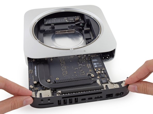
Carefully slide the logic board assembly out of the Mac mini, minding any cables that may get caught.
-
-
Este passo não foi traduzido. Ajude a traduzi-lo
-
Use tweezers or your fingers to pull the clip away from the AC-in socket, and remove it from the Mac mini.
-
-
Este passo não foi traduzido. Ajude a traduzi-lo
-
To free the power supply from the case, grab the AC-In connector, which acts like a latch.
-
Rotate the AC-In connector 90 degrees counter-clockwise.
-
-
Este passo não foi traduzido. Ajude a traduzi-lo
-
Remove the 8 mm T6 screw securing the power supply.
-
-
Este passo não foi traduzido. Ajude a traduzi-lo
-
Slide the power supply out of the mini, minding any cables that may get caught.
-
-
Este passo não foi traduzido. Ajude a traduzi-lo
-
Remove the single 8 mm T6 screw securing the drive tray.
-
-
Este passo não foi traduzido. Ajude a traduzi-lo
-
Remove the four (two on each side) 6.5 mm T8 screws securing the hard drive to the drive tray.
-
-
Este passo não foi traduzido. Ajude a traduzi-lo
-
Lift the hard drive up and remove it from the drive tray.
-
-
Este passo não foi traduzido. Ajude a traduzi-lo
-
Lift up the ribbon cable and carefully peel away the black tape underneath. It secures the SATA cable connector to the PCB of the hard drive. Failing to remove the tape will almost surely cause the contacts soldered to the flex cable to rip from the connector housing, as the retention force of the contacts in the housing is quite low.
-
Pull the SATA cable connector straight out of the hard drive.
-
Carefully peel off the two black, square-shaped sticky pads (one visible in picture) from the corners of the hard drive, and stick them to your new hard drive in the same locations.
-


Cancelar: não concluí este guia.
1079 outras pessoas executaram este guia.


225 comentários
Hello, the following hard drive goes on the Mac Mini ??
no problem. but if you can get a evo 850 or a pro for the 2014 is better
All in all, this was a fairly terrifying process, however this guide was a massive help! Thankyou!!
This is exactly the reason I purchased their tools. They offer these guides which have helped me save several of my computers and a couple of my phones over the years. The $70 was a small price to pay for the help and I love the tools.
Ordered kit which arrived very quickly from Germany to UK. Only problem with taking it apart was with the IR sensor was difficult to lift up and I ended up pulling the whole fitting off glued it back on but now have no working IR sensor or front light but everything else works fine. Swapped SLOW HDD for SSD and now my Mac MIni is flying.