Ir para o conteúdo principal

Mac Mini Late 2014 Logic Board Assembly Replacement

Pré-requisito somente
Este guia destina-se apenas a ser usado como pré-requisito para outros guias. É incompleto por si só.

O que você precisa

  1. Mac Mini Late 2014 Logic Board Assembly Replacement, Logic Board Assembly: passo 1, imagem 1 %32
    • Remove the 2.6 mm T6 screw securing the SATA cable connector bracket.

  2. Mac Mini Late 2014 Logic Board Assembly Replacement: passo 2, imagem 1 %32 Mac Mini Late 2014 Logic Board Assembly Replacement: passo 2, imagem 2 %32
    • Remove the SATA cable connector bracket.

  3. Mac Mini Late 2014 Logic Board Assembly Replacement: passo 3, imagem 1 %32 Mac Mini Late 2014 Logic Board Assembly Replacement: passo 3, imagem 2 %32
    • Use the flat end of a spudger to lift the SATA cable connector up off of its socket on the logic board.

  4. Mac Mini Late 2014 Logic Board Assembly Replacement: passo 4, imagem 1 %32 Mac Mini Late 2014 Logic Board Assembly Replacement: passo 4, imagem 2 %32
    • Use the tip of a spudger to disconnect the IR sensor cable connector by prying it straight up from its socket.

  5. Mac Mini Late 2014 Logic Board Assembly Replacement: passo 5, imagem 1 %32
    • The following three steps only apply to Mac minis equipped with a PCIe SSD. Skip the next three steps if your Mac mini only has a hard drive.

    • Remove the two 2.6 mm T6 screws securing the PCIe SSD cable bracket.

  6. Mac Mini Late 2014 Logic Board Assembly Replacement: passo 6, imagem 1 %32 Mac Mini Late 2014 Logic Board Assembly Replacement: passo 6, imagem 2 %32
    • Remove the PCIe SSD cable bracket.

  7. Mac Mini Late 2014 Logic Board Assembly Replacement: passo 7, imagem 1 %32 Mac Mini Late 2014 Logic Board Assembly Replacement: passo 7, imagem 2 %32
    • Lift the PCIe SSD connector up off its socket.

  8. Mac Mini Late 2014 Logic Board Assembly Replacement: passo 8, imagem 1 %32
    • Remove the single 16 mm T6 screw securing the logic board.

  9. Mac Mini Late 2014 Logic Board Assembly Replacement: passo 9, imagem 1 %32
    Ferramenta utilizada nesse passo:
    Mac mini Logic Board Removal Tool
    $4.99
    Comprar
    • To remove the logic board, the two cylindrical rods of the Mac mini Logic Board Removal Tool must be inserted into the holes highlighted in red. Inserting instruments into any logic board holes other than the ones highlighted in red may destroy the logic board.

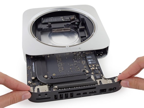
    • Insert the Mac mini Logic Board Removal Tool into the two holes highlighted in red. Be sure the rods make contact with the case under the logic board before proceeding.

  10. Mac Mini Late 2014 Logic Board Assembly Replacement: passo 10, imagem 1 %32 Mac Mini Late 2014 Logic Board Assembly Replacement: passo 10, imagem 2 %32 Mac Mini Late 2014 Logic Board Assembly Replacement: passo 10, imagem 3 %32
    • Carefully pull the tool toward the I/O board. The logic board and I/O board assembly should slightly slide out of the outer case.

    • Cease prying when the removal tool makes contact with the opening in the rear case.

    • Remove the Mac mini Logic Board Removal tool.

  11. Mac Mini Late 2014 Logic Board Assembly Replacement: passo 11, imagem 1 %32 Mac Mini Late 2014 Logic Board Assembly Replacement: passo 11, imagem 2 %32
    • Pull the DC-In cable connector straight out of its socket on the logic board.

  12. Mac Mini Late 2014 Logic Board Assembly Replacement: passo 12, imagem 1 %32 Mac Mini Late 2014 Logic Board Assembly Replacement: passo 12, imagem 2 %32
    • Carefully slide the logic board assembly out of the Mac mini, minding any cables that may get caught.

Conclusão

To reassemble your device, follow these instructions in reverse order.

Uma outra pessoa concluiu este guia.

Sam Goldheart

Membro desde: 10/18/12

465.116 Reputação

Autoria de 538 guias

Equipe

iFixit Membro de iFixit

Staff

Membros da 135

Autoria de 16.475 guias

0 comentários

Adicione um comentário

Exibir estatísticas:

Últimas 24 horas: 0

Últimos 7 dias: 0

Últimos 30 dias: 0

Duração total: 566