Esta versão pode conter edições incorretas. Mude para o último instantâneo verificado.
O que você precisa
-
Este passo não foi traduzido. Ajude a traduzi-lo
-
Remove these three Phillips #1 screws:
-
Two 10mm screws.
-
One 7mm screw.
-
-
-
Este passo não foi traduzido. Ajude a traduzi-lo
-
Using your fingers, lower the rubber boot to reveal two screws underneath the joystick.
-
Remove the two 10mm Phillips #1 screws.
-
-
Este passo não foi traduzido. Ajude a traduzi-lo
-
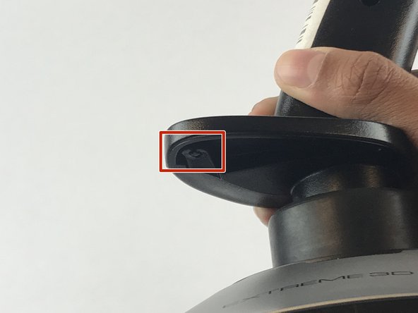
Pull apart the joystick chassis by hand.
-
Release this clip located underneath the hand rest
-


Cancelar: não concluí este guia.
6 outras pessoas executaram este guia.
Equipe

USF Tampa, Team S7-G1, Passmore Spring 2018 Membro de USF Tampa, Team S7-G1, Passmore Spring 2018
USFT-PASSMORE-S18S7G1
Membros da 4
Autoria de 7 guias
2 comentários
yeah but i got this far before looking at the site, and what i really want to see is how the cotter ring pin is set on the shaft that enables the z-rot instead of locking it down.
if you havent worked it out already, the Z-rot spring needs spread across a little 3/8 inch tab, otherwise it will lock the axis a few degrees off center