Esta versão pode conter edições incorretas. Mude para o último instantâneo verificado.
O que você precisa
-
Este passo não foi traduzido. Ajude a traduzi-lo
-
Use a Phillips #0 screwdriver to remove the nine 6mm screws from the larger back plate.
-
-
Este passo não foi traduzido. Ajude a traduzi-lo
-
Turn your laptop back over, open it, and use the plastic opening tool on the recessed notch to gently pry each side and lift the keyboard plate up.
-
-
Este passo não foi traduzido. Ajude a traduzi-lo
-
Unlock the keyboard ZIF connector to release the keyboard flex cable.
-
Unlock the touchpad ZIF connector to release the touchpad flex cable.
-
Carefully pull both flex cables out of the ZIF connectors.
-
Remove the keyboard plate up and place it to the side.
-
-
-
Este passo não foi traduzido. Ajude a traduzi-lo
-
Unplug the battery cable by pulling it towards the battery.
-
-
Este passo não foi traduzido. Ajude a traduzi-lo
-
Use the Phillips #0 screwdriver to remove the three 6mm screws from the battery.
-
-
Este passo não foi traduzido. Ajude a traduzi-lo
-
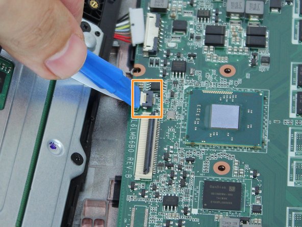
Using the black nylon spudger, lift up the grey bar of the ZIF connector attached to the motherboard located in the bottom right corner.
-
Pull out the ribbon cable connecting the motherboard to the daughterboard.
-
-
Este passo não foi traduzido. Ajude a traduzi-lo
-
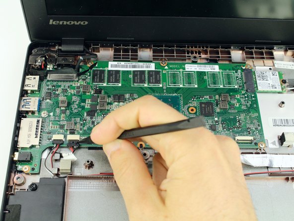
Use the spudger to coax the sliding speaker cables toward you, out of the motherboard attachments.
-
-
Este passo não foi traduzido. Ajude a traduzi-lo
-
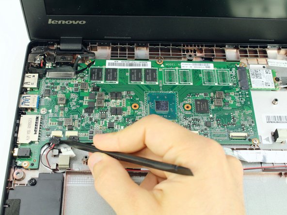
Use the flat end of the spudger to pop up the display cable connector from the motherboard.
-
-
Este passo não foi traduzido. Ajude a traduzi-lo
-
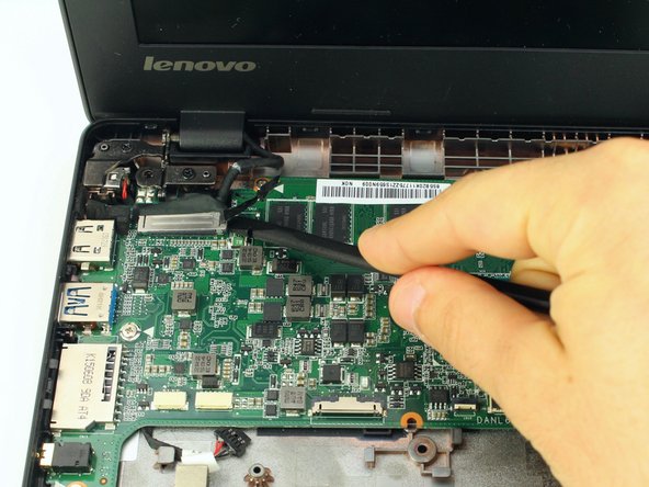
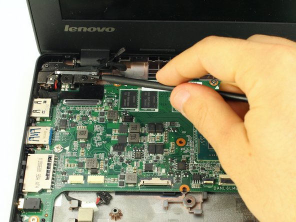
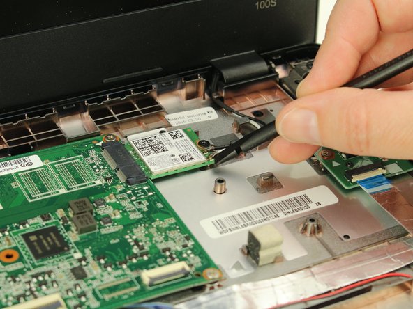
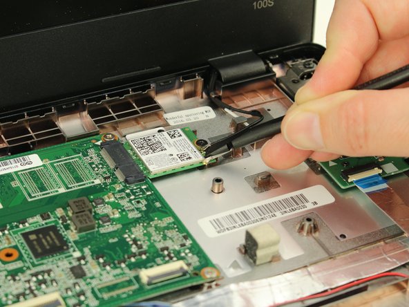
Pry up the coaxial antenna cables from the wifi card with the spudger.
-
-
Este passo não foi traduzido. Ajude a traduzi-lo
-
Use your Phillips #0 screwdriver to remove six 3.7mm screws from the motherboard.
-
Use the same Phillips #0 screwdriver to remove one 3.2mm screw from the wireless card.
-
Wiggle the motherboard gently out from the case. It should come out towards you and slightly to the right.
-