O que você precisa
-
-
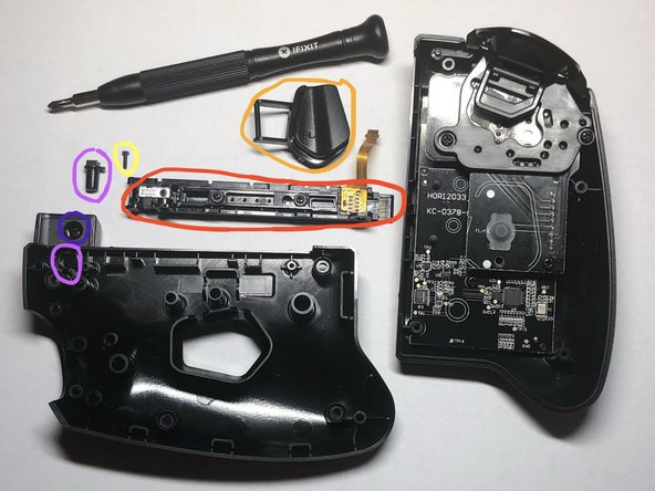
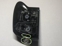
Flip over the left controller and locate the four screws.
-
Remove the four PH0 screws.
 Pergunte ao FixBot
-
-
-
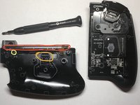
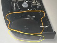
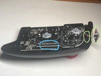
Lift the back half slightly off the front half and fold it open along the left edge.
-
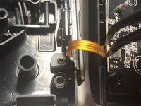
The ribbon cable is circled in the second image.
-
-
Ferramenta utilizada neste passo:Tweezers$4.99
-
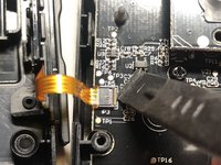
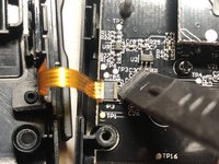
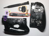
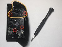
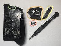
Use a plastic spudger to flip the ribbon cable latch up as shown in the first two images.
-
Remove the ribbon cable from the slot by pulling gently to the left with tweezers or fingers.
-
-
-
-
Remove one PH00 screw that is securing the rail to the back half.
-
The FL button can be removed by placing a lever/spudger under the circled area.
-
The rail connector can be removed once the yellow circled screw is removed.
-
The button that releases the buckle lock can be removed after the rail and goes in the hole circled on the back half of the controller.
-
The one remaining screw does not need to be removed as it only secures a bit of plastic.
-
-
-
Remove the three PH00 screws.
-
Pry out the metal cover over the buckle lock. Be gentle so as not to bend the metal.
-
The spring loaded buckle lock can then be removed. NOTE: Do not loose the spring when disassembling. Reassembly can be tricky because the spring needs to be compressed to get back in place.
-
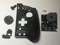
The plastic cover over the holes in the middle of the rail can be removed. This is where SL, SR, and connect buttons would be on a normal Joy Con controller and also the lights indicating which controller number it is.
-
-
-
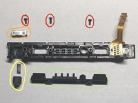
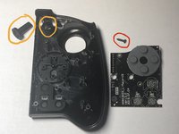
The ZL button can be removed once the red circled screws are removed.
-
The L button is underneath the ZL button and is easily removed once the ZL button is out of the way. There is a small hole that one end of the L button fits into.
-
Remove four PH0 screws, two that hold in the ZL button plastics and one on the top button board and one of the two screws securing the main motherboard.
-
Warning: Do not try to remove the top button board before you remove this small button board in the next step.
-
-
-
The small L button board is slid into a slot and has delicate wires that connect it to the top button board.
-
Clasp on both sides of the small L button board with your fingers and wiggle it out.
-
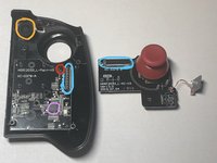
The top button board is connected to the main motherboard with the circled connector.
-
-
-
Here you can see the connector that joins the top button board and main motherboard. Pull directly up on the top button board and the entire board will come loose. This board also has the joystick control on it.
-
One remaining screw appears from under the top button board; remove.
-
The minus button can be removed. Notice the orientation and that there are two pin holes that the front half plastics poke through.
-
The processor for the controller can be seen on the main motherboard. See the details in Step 9.
-
The main motherboard can be removed and as well as all remaining rubberized/plastic buttons.
-
-
-
This is the only microchip on any of the boards.
-
This is a MM32L052NT chip from China that is a 32 bit ARM Cortex(TM) M0 with 48MHz CPU, 32K NVRAM, 4K SRAM, and various I/O interfaces.
-
Datasheet available here: http://www.mm32mcu.com/userfiles/images/...
-


To reassemble your device, follow these instructions in reverse order.
Cancelar: não concluí este guia.
5 outras pessoas executaram este guia.
7Comentários do guia
This was very helpful! Thank you for the tutorial
Would anyone like to venture a guess as to whether I could snag a generic joystick to solder in place of the existing one? Maybe it has a part number printed on it or the corresponding board? The left thumbstick isn't working correctly on mine after approximately a year of use. I used to replace drifting thumbsticks in Xbox 360 controllers without much trouble at all and I'd love to salvage my Split Pad if at all possible.
Ryan, I have previously commented on another post that the joystick looks like an exact match for the Xbox 360 controller joystick. I would suggest you give it a try.
Thank you for the writing this guide. It is very helpful. Is there anywhere you know of that sells replacement ribbon cables? It has detached from the latch and I am not sure if it is salvageable.
Thanks a lot.
Doubtful that you'd be able to find a replacement unless you have another set of the same controllers. The ribbon cable is supposed to come out of the latched cable connector like shown in Step 3. You should be able to put it back into the cable connector and flip the latch back down to hold it in. The cable connector is very flat and the ribbon cable only fits in from the one direction. Hope that helps.