Esta versão pode conter edições incorretas. Mude para o último instantâneo verificado.
O que você precisa
-
Este passo não foi traduzido. Ajude a traduzi-lo
-
Remove the back cover by firmly pressing against the raised lip on the back panel. Slide the cover towards the top of the phone.
-
-
Este passo não foi traduzido. Ajude a traduzi-lo
-
Remove the battery by placing your fingernail or a opening tool in the recessed edge and lift the battery out.
-
-
Este passo não foi traduzido. Ajude a traduzi-lo
-
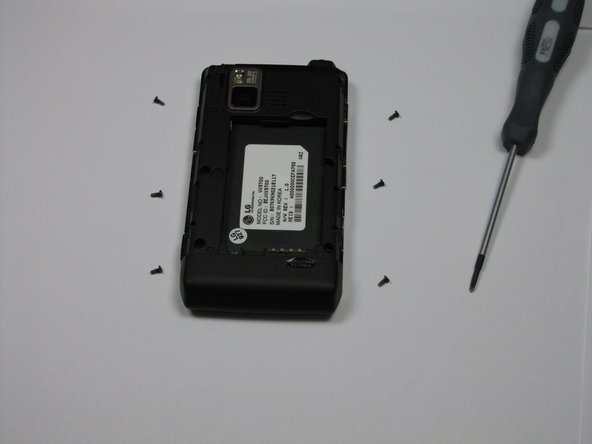
Use the #00 screwdriver to remove the six 4mm phillips screws located around the edges of the phone.
-
-
Este passo não foi traduzido. Ajude a traduzi-lo
-
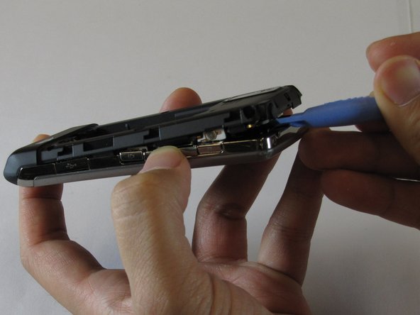
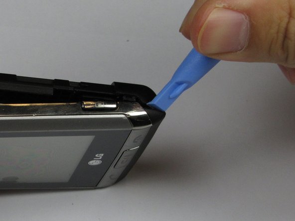
Lift the back plastic cover off by moving the opening tool around the edges of the phone.
-
Wedging the opening tool in several places on the bottom of the phone will help release small tabs that hold the back to the front frame.
-
-
Este passo não foi traduzido. Ajude a traduzi-lo
-
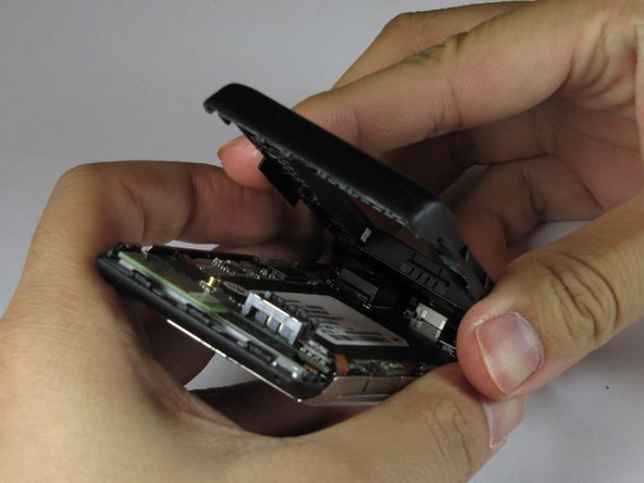
Pull off the back plastic panel.
-
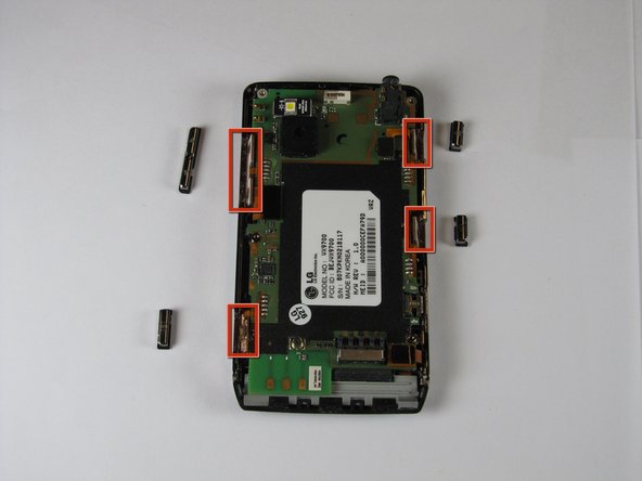
Remove the buttons from the edge of the frame. The buttons are [lock], [volume control], [speaker], and [camera].
-
-
Este passo não foi traduzido. Ajude a traduzi-lo
-
Disconnect the three ribbon connectors from the motherboard.
-
-
Este passo não foi traduzido. Ajude a traduzi-lo
-
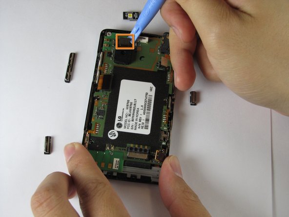
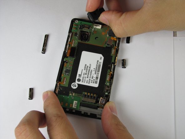
Remove the LED.
-
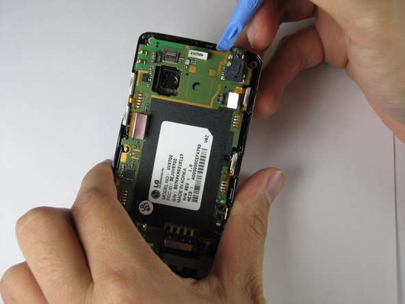
Remove the camera connector.
-
Remove the camera sensor from the logic board. Squeeze the sides of the camera sensor firmly and pull straight up.
-
-
-
Este passo não foi traduzido. Ajude a traduzi-lo
-
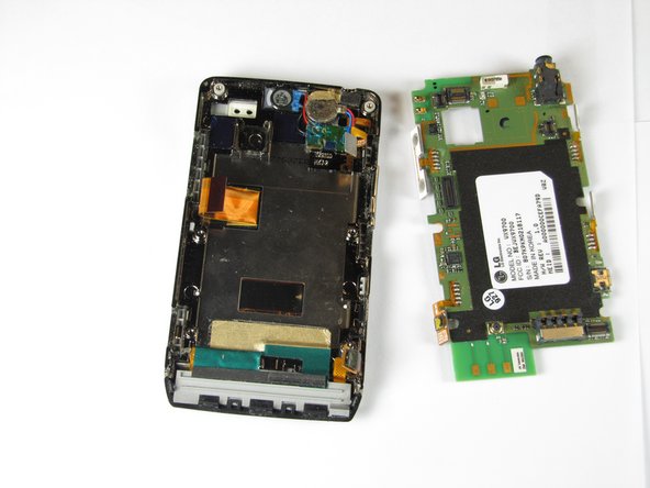
Use the opening tool to lift up the green logic board in all areas and remove it.
-
-
Este passo não foi traduzido. Ajude a traduzi-lo
-
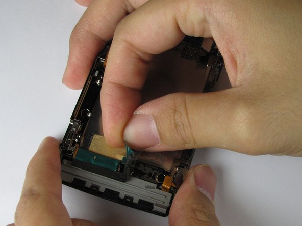
Peel off the gold and green tape near the bottom of the phone.
-
Peel off the blue tape covering the speaker connector.
-
Peel off the gold tape to the left of the earpiece speaker.
-
-
Este passo não foi traduzido. Ajude a traduzi-lo
-
Lift up the orange ribbon cable in the bottom left corner of the device.
-
Peel off the small piece of gold tape underneath the orange component back.
-
-
Este passo não foi traduzido. Ajude a traduzi-lo
-
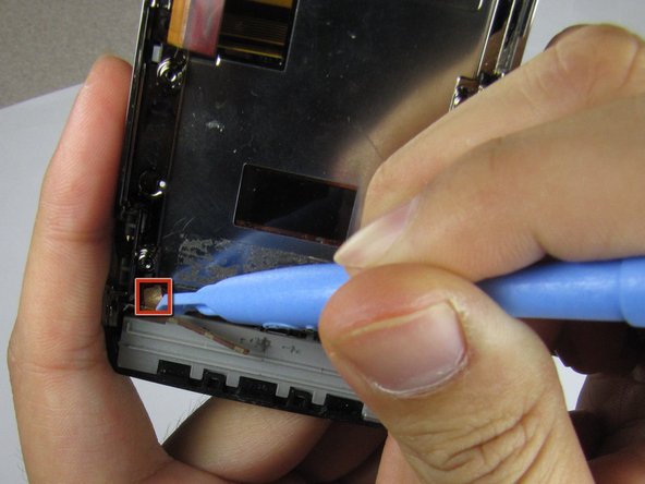
Undo the clips that attach the black plastic strip to the frame of the phone.
-
Pry the plastic strip away from the phone, using an opening tool, until it detaches.
-
-
Este passo não foi traduzido. Ajude a traduzi-lo
-
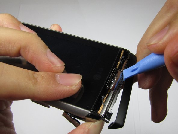
Pry the button panel from the device, starting where the screen and panel connect, until the panel detaches.
-
-
Este passo não foi traduzido. Ajude a traduzi-lo
-
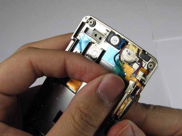
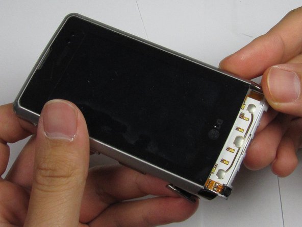
Rotate the phone upside down with the back facing you.
-
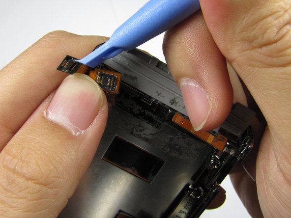
Using your finger to hold the bottom connector in place, use the opening tool to remove the top connector.
-
-
Este passo não foi traduzido. Ajude a traduzi-lo
-
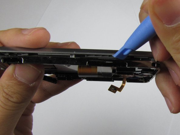
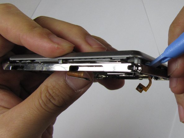
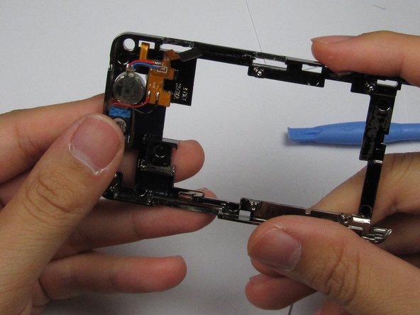
Using the opening tool, pry the frame from the device, starting at the open edges at the bottom of the device, and working your way around.
-
-
Este passo não foi traduzido. Ajude a traduzi-lo
-
Gently separate the top of the frame from the back of the device, without completely detaching at the bottom, as shown in the third picture.
-
-
Este passo não foi traduzido. Ajude a traduzi-lo
-
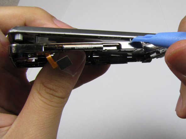
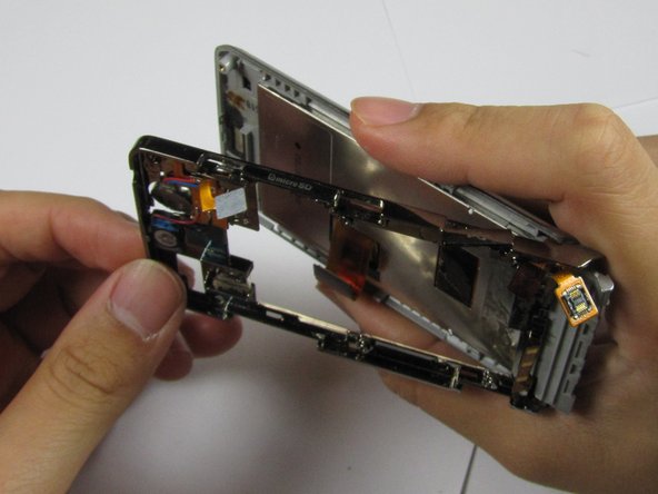
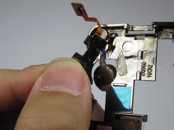
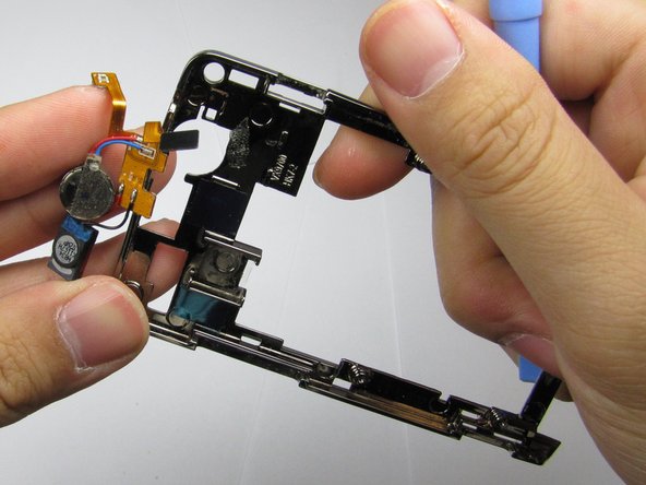
Remove both connectors from the frame. Fold back the L-shaped connector and slide the second connector through the hole in the metal frame.
-
Remove the frame from the plastic panel.
-
-
Este passo não foi traduzido. Ajude a traduzi-lo
-
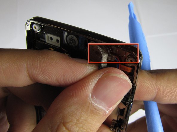
Using the opening tool, pry the orange connector pad that is securing the earpiece to the frame, away from the device, until it detaches.
-
-
Este passo não foi traduzido. Ajude a traduzi-lo
-
Pry the rest of the orange connector pad --on the opposite side of the device-- away from the frame, and carefully remove the entire earpiece.
-
-
Este passo não foi traduzido. Ajude a traduzi-lo
-
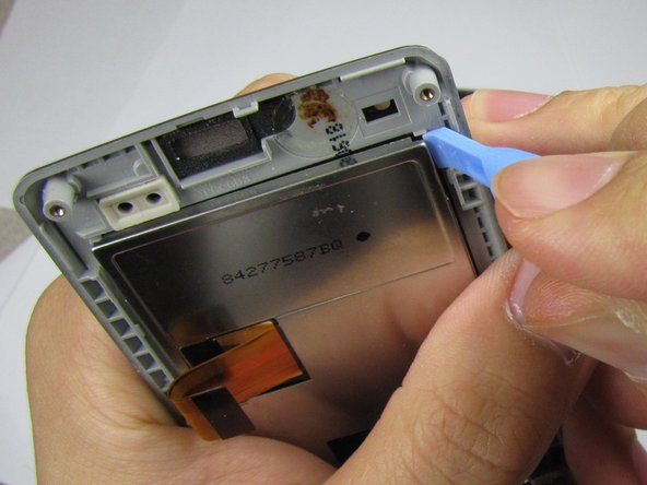
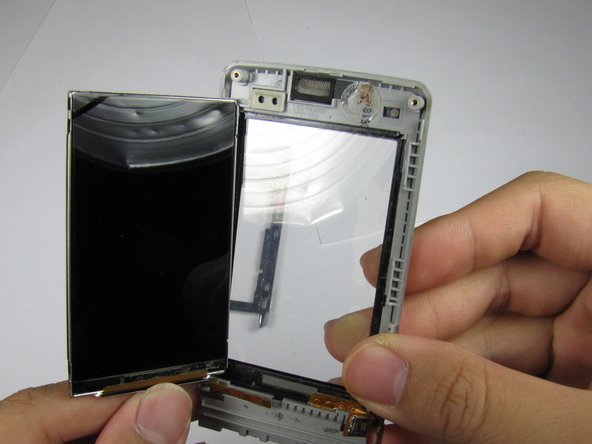
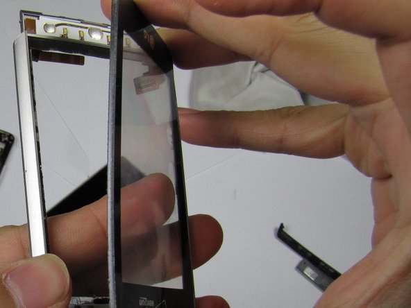
Using the opening tool, carefully pry the digitizer (the black-rimmed piece) away from the silver frame.
-
Remove the digitizer carefully without breaking the connector.
-
-
Este passo não foi traduzido. Ajude a traduzi-lo
-
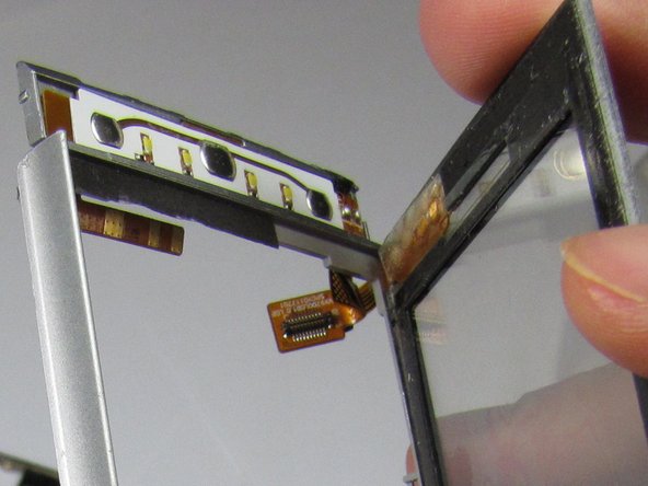
Carefully remove the digitizer connector from the plastic frame. There is a slot that the connector slides through.
-


Cancelar: não concluí este guia.
Uma outra pessoa concluiu este guia.
Equipe

Cal Poly, Team 9-4, Regan Winter 2012 Membro de Cal Poly, Team 9-4, Regan Winter 2012
CPSU-REGAN-W12S9G4
Membros da 5
Autoria de 10 guias