Esta versão pode conter edições incorretas. Mude para o último instantâneo verificado.
O que você precisa
-
Este passo não foi traduzido. Ajude a traduzi-lo
-
Turn your speaker upside down and insert the plastic opening tool vertically into the slit in the front cover.
-
Slowly pull the plastic opening tool outward to remove the four clips holding the covering in place.
-
Repeat this process for all four edges of the front cover.
-
-
Este passo não foi traduzido. Ajude a traduzi-lo
-
Pull apart your cover gently from both sides and remove it from the speaker housing.
-
-
Este passo não foi traduzido. Ajude a traduzi-lo
-
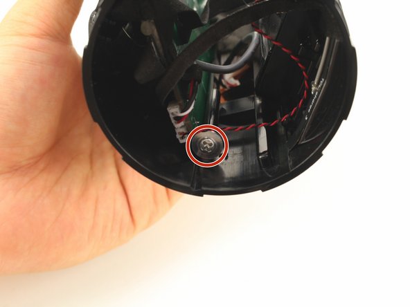
Remove the two 8mm Phillips #1 screws from the tabs.
-
NOTE: There may be only one screw.
-
-
Este passo não foi traduzido. Ajude a traduzi-lo
-
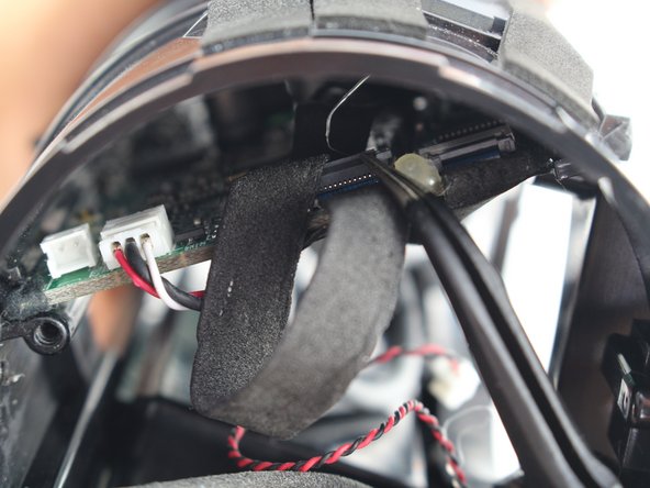
Insert the plastic opening tools underneath both tabs.
-
-
Este passo não foi traduzido. Ajude a traduzi-lo
-
Twist and pull open the passive radiator. The left radiator twists off clockwise; the right counterclockwise.
-
-
Este passo não foi traduzido. Ajude a traduzi-lo
-
Repeat all previous steps for the other passive radiator.
-
NOTE: only the right radiator needs to be removed for changing the battery.
-
-
Este passo não foi traduzido. Ajude a traduzi-lo
-
Remove the eight 10mm Phillips #1 screws from around the two front speakers.
-
-
Este passo não foi traduzido. Ajude a traduzi-lo
-
Pull gently on one of the speakers so it is outside of the housing. Be careful as it is still attached with the wires to the motherboard.
-
-
Este passo não foi traduzido. Ajude a traduzi-lo
-
Press the small metal tab on the speaker connector with a Phillips #000 screwdriver and gently pull the connector apart.
-
-
-
Este passo não foi traduzido. Ajude a traduzi-lo
-
Grab the bundled cable connector that joins the speakers to the motherboard with tweezers. Gently pull the connector free.
-
-
Este passo não foi traduzido. Ajude a traduzi-lo
-
Now that the second speaker is disconnected from the motherboard, pull the speaker and wires out of the housing.
-
-
Este passo não foi traduzido. Ajude a traduzi-lo
-
Remove the six 8mm Phillips #1 screws from the outer battery cover.
-
Peel the outer battery cover away from the speaker housing.
-
-
Este passo não foi traduzido. Ajude a traduzi-lo
-
Remove the seven 8mm Phillips #1 screws from interior battery cover.
-
Remove the interior battery cover.
-
-
Este passo não foi traduzido. Ajude a traduzi-lo
-
Pull gently to disconnect the bundled cable connector in the side of the speaker. This action will separate the battery from the motherboard.
-
-
Este passo não foi traduzido. Ajude a traduzi-lo
-
Pull the battery and battery cable out from their housing.
-
-
Este passo não foi traduzido. Ajude a traduzi-lo
-
Take out the four 8mm Phillips #1 screws out of the port bay cover.
-
Wedge your plastic opening tool around the port bay to remove it.
-
-
Este passo não foi traduzido. Ajude a traduzi-lo
-
Disconnect the two bundled cable connector from the port bay.
-
-
Este passo não foi traduzido. Ajude a traduzi-lo
-
Remove the three 8mm Phillips #1 screws from the port bay circuit board.
-
Pull the port bay cover off of the circuit board.
-
-
Este passo não foi traduzido. Ajude a traduzi-lo
-
Desolder the USB, MicroUSB, or AUX port off of the circuit board.
-
-
Este passo não foi traduzido. Ajude a traduzi-lo
-
Remove the two 9mm Phillips #1 screws holding in the sides of the motherboard.
-
-
Este passo não foi traduzido. Ajude a traduzi-lo
-
Gently pull the bundled cable connector on the motherboard.
-
-
Este passo não foi traduzido. Ajude a traduzi-lo
-
Gently pull the golden connector off of the motherboard.
-
-
Este passo não foi traduzido. Ajude a traduzi-lo
-
Flip open the top flap on the two ZIF connectors.
-
Gently pull out the ZIF connector cables with tweezers.
-


Cancelar: não concluí este guia.
11 outras pessoas executaram este guia.
Equipe

Cal Poly, Team S13-G1, White Fall 2018 Membro de Cal Poly, Team S13-G1, White Fall 2018
CPSU-WHITE-F18S13G1
Membros da 3
Autoria de 26 guias
10 comentários
Internation version is different. There are no screws for passive radiotors.
You have to twist it. I have to managed to get it open because there is no video on youtube (I can’t find any)
If that even is Charge 3.
My JBL charge 3 is not charging …please give me idea to fix ..but it’s working perfectly only
My jbl charge are charging but it won't turn on…… i have tried several times to turn it on but it won't turn…… hoping for solutions……