Esta versão pode conter edições incorretas. Mude para o último instantâneo verificado.
O que você precisa
-
Este passo não foi traduzido. Ajude a traduzi-lo
-
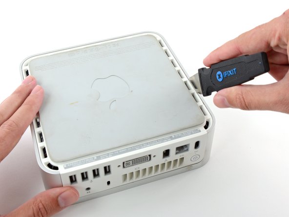
Power down your Mac mini, disconnect all of the cables, and flip it over.
-
Insert the Jimmy into the crack between the aluminum top housing and the plastic lower housing.
-
The Jimmy should reach a stop about 3/8" down.
-
-
Este passo não foi traduzido. Ajude a traduzi-lo
-
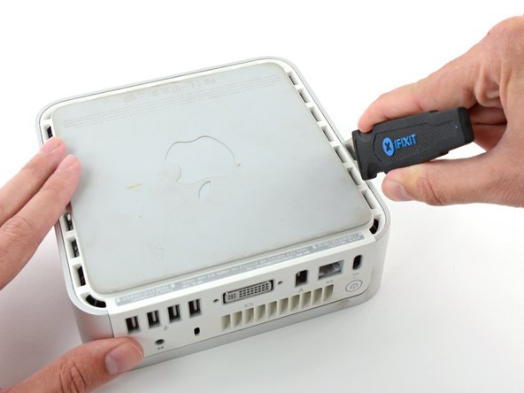
Gently bend the Jimmy outwards to pry the crack open a little larger and lift the lower housing up a small amount.
-
-
Este passo não foi traduzido. Ajude a traduzi-lo
-
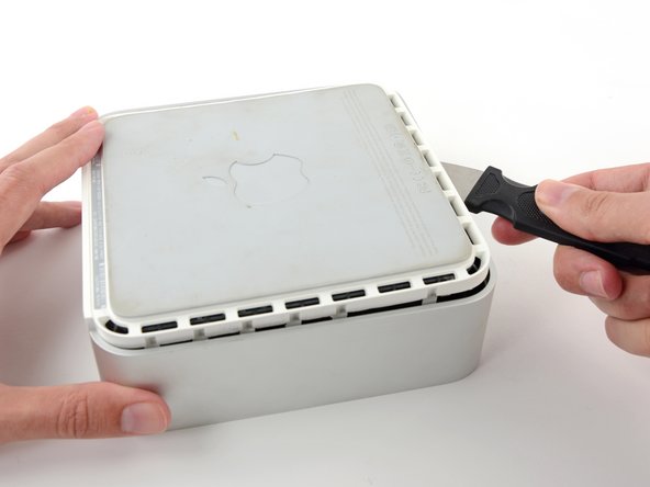
Once you have the first side free, rotate the Mac mini and start prying up on the front edge.
-
Use the same prying motion to both bend the clips inward and lift the lower housing up out of the top housing.
-
-
Este passo não foi traduzido. Ajude a traduzi-lo
-
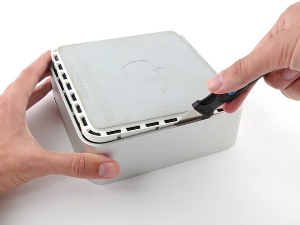
You may need to move the Jimmy along the edge to pry up all of the clips. Be patient and do a little bit at a time.
-
-
Este passo não foi traduzido. Ajude a traduzi-lo
-
Keep working around the perimeter, freeing the clips along the final edge.
-
-
Este passo não foi traduzido. Ajude a traduzi-lo
-
Flip the Mac mini back over and lift the top housing off of the lower housing.
-
-
Este passo não foi traduzido. Ajude a traduzi-lo
-
Slightly squeeze the two retaining arms toward each other and lift the AirPort antenna off its post.
-
-
Este passo não foi traduzido. Ajude a traduzi-lo
-
Use the tip of a spudger to slightly lift the left side of the ZIF cable lock up from its socket.
-
-
Este passo não foi traduzido. Ajude a traduzi-lo
-
Lift the audio board ribbon cable up out of its socket.
-
-
-
Este passo não foi traduzido. Ajude a traduzi-lo
-
Use a pair of tweezers to lift the hard drive thermal sensor cable connector up off its socket on the logic board.
-
-
Este passo não foi traduzido. Ajude a traduzi-lo
-
Remove the recessed Phillips screw near the power button securing the internal frame to the bottom housing.
-
-
Este passo não foi traduzido. Ajude a traduzi-lo
-
Remove the recessed Phillips screw near the sleep light securing the internal frame to the bottom housing.
-
-
Este passo não foi traduzido. Ajude a traduzi-lo
-
Remove the Phillips screw from the internal frame near the Bluetooth antenna.
-
-
Este passo não foi traduzido. Ajude a traduzi-lo
-
Remove the Phillips screw near the audio ports securing the internal frame to the bottom case.
-
-
Este passo não foi traduzido. Ajude a traduzi-lo
-
Gently lift the internal frame up from the bottom housing, minding the AirPort antenna and any other cables that may get caught.
-
-
Este passo não foi traduzido. Ajude a traduzi-lo
-
Remove the Bluetooth antenna from the internal frame by pushing up on both sides of the board as close to the center post as possible.
-
-
Este passo não foi traduzido. Ajude a traduzi-lo
-
Remove the two Phillips screws securing the optical drive to the internal frame.
-
-
Este passo não foi traduzido. Ajude a traduzi-lo
-
Turn the mini 180 degrees and remove the two Phillips screws securing the optical drive to the internal frame on the other side.
-
-
Este passo não foi traduzido. Ajude a traduzi-lo
-
Remove the two Phillips screws securing the interconnect board to the optical drive.
-
-
Este passo não foi traduzido. Ajude a traduzi-lo
-
Use the flat end of a spudger to separate the interconnect board from the optical drive.
-
-
Este passo não foi traduzido. Ajude a traduzi-lo
-
Remove the plastic spacer from the optical bay hard drive enclosure by pressing in on one of the clips on either side and lifting it up and out of the enclosure.
-
-
Este passo não foi traduzido. Ajude a traduzi-lo
-
Make sure that the hard drive connectors are facing down before placing it into the enclosure.
-
Gently place the hard drive into the enclosure's hard drive slot.
-
While firmly holding the enclosure in place with one hand, use your other hand to press the hard drive into the enclosure connectors.
-
-
Este passo não foi traduzido. Ajude a traduzi-lo
-
Once the hard drive is snug, reinsert the plastic spacer while holding the hard drive against the bottom of the enclosure.
-
-
Este passo não foi traduzido. Ajude a traduzi-lo
-
Use two Phillips #1 screws to secure the drive to its enclosure.
-
-
Este passo não foi traduzido. Ajude a traduzi-lo
-
Attach the optical drive bracket to the new enclosure with two Phillips #0 screws.
-
Reconnect any cables you have removed from the original optical drive onto the optical bay enclosure.
-
-
Este passo não foi traduzido. Ajude a traduzi-lo
-
Align the cable's SATA connector with the drive's port and plug in securely.
-
Plug the USB connector into your laptop and your optical drive is ready for use.
-


Cancelar: não concluí este guia.
28 outras pessoas executaram este guia.


6 comentários
Here's something important to be aware of. DVD Player will not function without a physical dvd drive installed. This is even if you use DVD image files, which I do. The explanation I got is that without that optical drive DVD Player can't check regions. If you want to watch DVDs on your mac mini, even DVD image files, don't remove the optical drive.
Or, if you want to play dvd files just use vlc player... if vlc can't play it, it can't be played.
cort -
Just added a 500 gig HD I had laying around to a 2007 Mac Mini I got on eBay.....worked like a charm. Thanks iFixit!
although my optical bay hard drive enclosure did not use or have the bracket shown above with two Phillips #0 screws. And the hard drive had a different attachment system. The screws did not come in from the bottom. They came in from the side....no matter still a great solution.