Esta versão pode conter edições incorretas. Mude para o último instantâneo verificado.
O que você precisa
-
Este passo não foi traduzido. Ajude a traduzi-lo
-
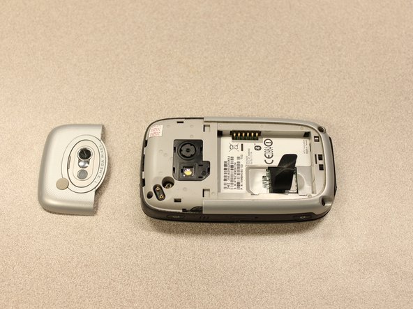
To expose the battery, remove the outer case with your fingernail.
-
Remove the battery by pulling the black tab.
-
-
Este passo não foi traduzido. Ajude a traduzi-lo
-
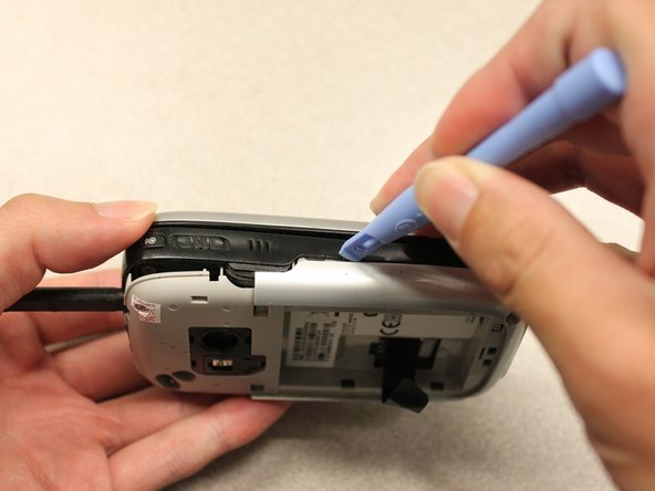
Insert the flat end of the spudger into the two notches on the back of the camera cover and pry them up.
-
-
Este passo não foi traduzido. Ajude a traduzi-lo
-
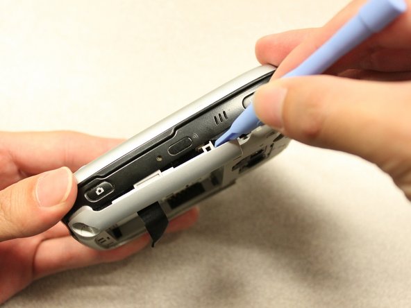
Work the spudger around the edges of the camera cover until it comes off.
-
-
Este passo não foi traduzido. Ajude a traduzi-lo
-
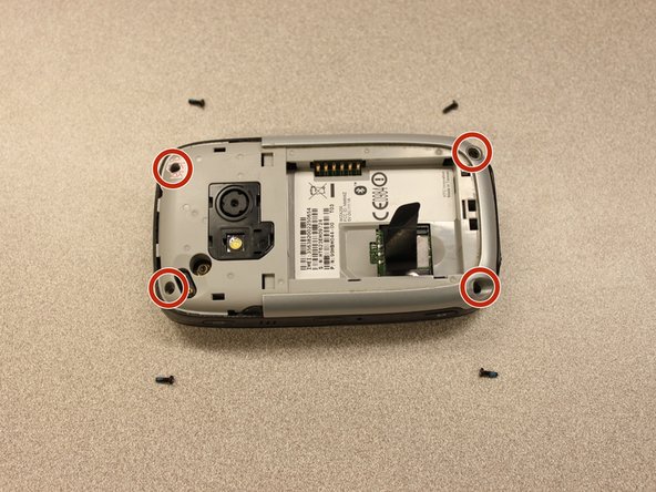
Remove the four 6 mm screws with the T5 Torx screwdriver.
-
-
Este passo não foi traduzido. Ajude a traduzi-lo
-
Insert the flat end of an iFixit opening tool between the side and inner covers to create a gap.
-
Work the tool around the edges until all the clips release.
-
-
Este passo não foi traduzido. Ajude a traduzi-lo
-
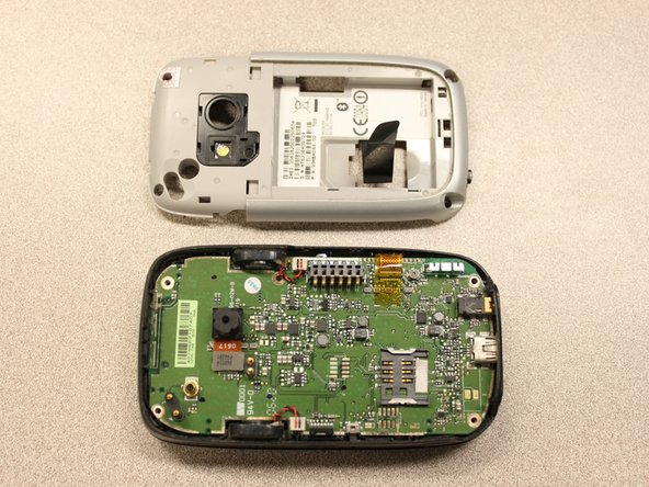
Once all the clips are open, remove the inner panel from the phone.
-
-
Este passo não foi traduzido. Ajude a traduzi-lo
-
-
Este passo não foi traduzido. Ajude a traduzi-lo
-
Using tweezers, flip the connector latch away from the motherboard.
-
Detach the flexible connection from under the connector latch.
-
-
Este passo não foi traduzido. Ajude a traduzi-lo
-
Lift the motherboard out of the case using the spudger.
-
Expose the underside of the motherboard using your hands.
-
-
Este passo não foi traduzido. Ajude a traduzi-lo
-
Remove the flexible connection from the motherboard.
-
-
Este passo não foi traduzido. Ajude a traduzi-lo
-
Remove the four 5mm screws with the T5 Torx screwdriver.
-
Remove the keyboard slider from the main body.
-
-
Este passo não foi traduzido. Ajude a traduzi-lo
-
Use the T5 Torx screwdriver to remove four 5mm screws that secure the back of the screen casing.
-
-
Este passo não foi traduzido. Ajude a traduzi-lo
-
Insert the plastic opening tool between the front panel and the rear panel and pry open to reach the screen.
-
-
Este passo não foi traduzido. Ajude a traduzi-lo
-
Once the rear panel is loose, lift it off of the front panel.
-
The flexible connection will pop loose.
-
-
Este passo não foi traduzido. Ajude a traduzi-lo
-
Unscrew the two 3mm phillips #0 screws from the bottom of the device that secure the rigid flex board to the screen panel.
-
-
Este passo não foi traduzido. Ajude a traduzi-lo
-
Unscrew the two 3mm phillips #0 screws from the top of the device that secure the rigid flex board to the screen panel.
-
-
Este passo não foi traduzido. Ajude a traduzi-lo
-
Unhinge the flexible connection and use the tweezers to disconnect.
-
-
Este passo não foi traduzido. Ajude a traduzi-lo
-
Now that the rigid flex board is loose, remove it from the screen.
-


Equipe

Cal Poly, Team 20-27, Maness Fall 2011 Membro de Cal Poly, Team 20-27, Maness Fall 2011
CPSU-MANESS-F11S20G27
Membros da 4
Autoria de 24 guias