Esta versão pode conter edições incorretas. Mude para o último instantâneo verificado.
O que você precisa
-
Este passo não foi traduzido. Ajude a traduzi-lo
-
Remove the rubber screw covers. If needed, use a thin object to help pry them off. There should be two of them on top of the phone. Skip this step if already removed.
-
Pry loose the metal cover near the camera lens, circled in the picture.
-
-
Este passo não foi traduzido. Ajude a traduzi-lo
-
Remove the battery cover.
-
Gripping the battery by the bottom, lift and remove it from the phone.
-
-
Este passo não foi traduzido. Ajude a traduzi-lo
-
After removing the rubber stoppers on top, there should be six exposed screws. Remove these using the T6 screwdriver.
-
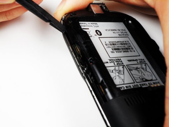
Next, use the spudger to loosen the case underneath the shiny metal edge. Go all the way around the phone until completely loosened.
-
After loosening the case, remove it.
-
-
-
Este passo não foi traduzido. Ajude a traduzi-lo
-
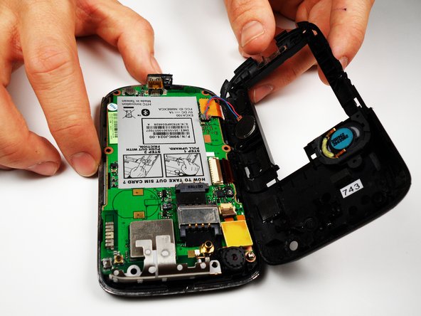
Remove the one remaining screw in the logic board.
-
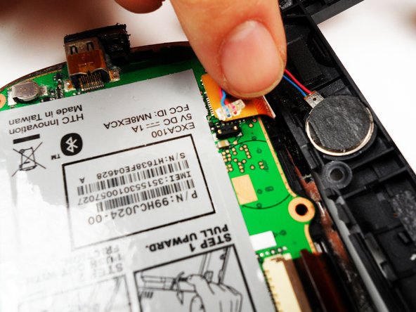
Unclip the wire that connects the back of the case to the logic board.
-
-
Este passo não foi traduzido. Ajude a traduzi-lo
-
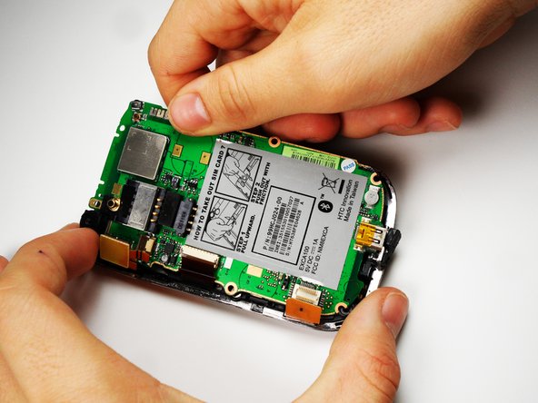
On the left side of the phone, there are three copper colored clips.
-
Unclip the bottom clip, thread the middle one through the logic board, and pull the top one out gently.
-
You can then lift the logic board out of the phone.
-
-
Este passo não foi traduzido. Ajude a traduzi-lo
-
Remove the metal frame. Slip out the copper clips still attached to the bottom frame from the frame carefully.
-
-
Este passo não foi traduzido. Ajude a traduzi-lo
-
Remove the metal backing to the keyboard using Phillip 00 screwdriver to remove the 3 screws.
-
After the screws are removed, take off the back cover of the keyboard.
-
You can now peel off the keyboard, and replace it. After the new keyboard is in place, reassemble the device.
-


Equipe

Cal Poly, Team 25-27, Garner Spring 2011 Membro de Cal Poly, Team 25-27, Garner Spring 2011
CPSU-GARNER-S11S25G27
Membros da 4
Autoria de 10 guias