Esta versão pode conter edições incorretas. Mude para o último instantâneo verificado.
O que você precisa
-
Este passo não foi traduzido. Ajude a traduzi-lo
-
Press and slide the battery cover tab to remove battery cover.
-
-
Este passo não foi traduzido. Ajude a traduzi-lo
-
Pull on the black tab to lift the battery out of the battery compartment.
-
-
Este passo não foi traduzido. Ajude a traduzi-lo
-
Remove the CF card by sliding it out of the slot at the top of the device.
-
-
Este passo não foi traduzido. Ajude a traduzi-lo
-
Press down and push the black side strips toward the top of the device to remove them.
-
-
-
Este passo não foi traduzido. Ajude a traduzi-lo
-
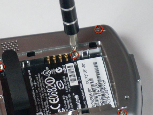
Using the T5 Torx screwdriver, remove all six screws on the back and all screws on each side of the device.
-
-
Este passo não foi traduzido. Ajude a traduzi-lo
-
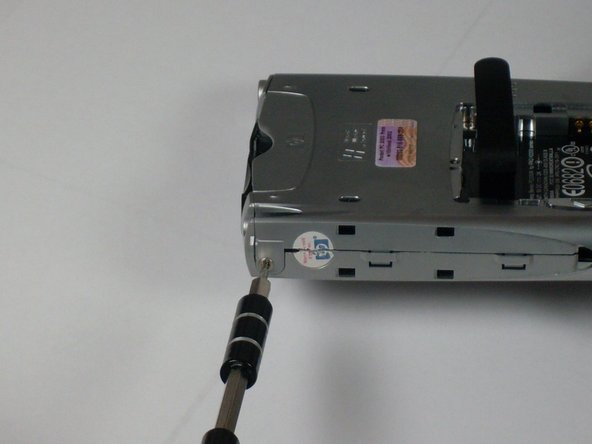
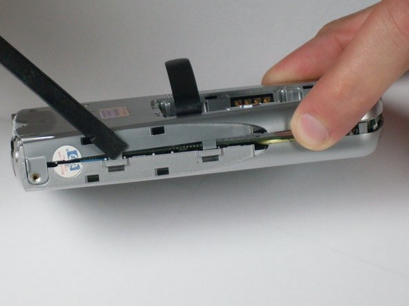
Remove the back faceplate by pushing and loosening the 4 side slots (2 on each side).
-
-
Este passo não foi traduzido. Ajude a traduzi-lo
-
Open the LCD connector, where the orange strip attaches to the main board.
-
-
Este passo não foi traduzido. Ajude a traduzi-lo
-
Carefully remove the orange LCD strip from the connector.
-
-
Este passo não foi traduzido. Ajude a traduzi-lo
-
Unscrew the 2 screws located at each top corner of the main board.
-
-
Este passo não foi traduzido. Ajude a traduzi-lo
-
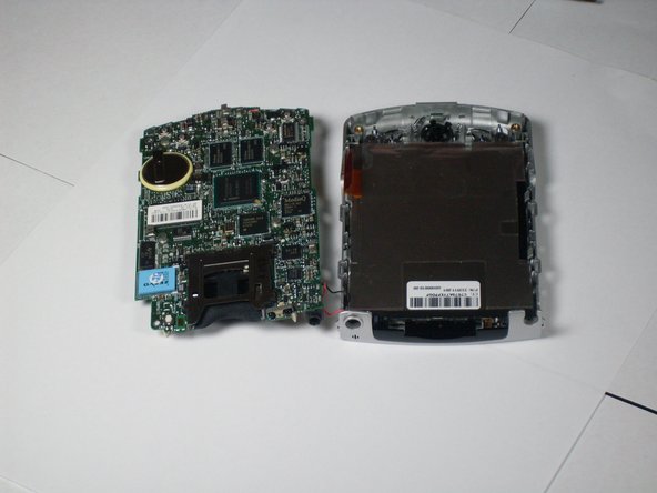
Remove the main board by pushing outward on the two tabs located on each side near the bottom of the device.
-
-
Este passo não foi traduzido. Ajude a traduzi-lo
-
Unscrew the two bottom screws on LCD screen that were previously located under the main board.
-
-
Este passo não foi traduzido. Ajude a traduzi-lo
-
Press on side tabs to loosen and remove the LCD screen.
-
-
Este passo não foi traduzido. Ajude a traduzi-lo
-
Remove the faceplate by unscrewing the green screw located on the top right of the front faceplate.
-


Equipe

Cal Poly, Team 4-12, Forte Winter 2010 Membro de Cal Poly, Team 4-12, Forte Winter 2010
CPSU-FORTE-W10S4G12
Membros da 3
Autoria de 5 guias