Esta versão pode conter edições incorretas. Mude para o último instantâneo verificado.
O que você precisa
-
Este passo não foi traduzido. Ajude a traduzi-lo
-
Shut down the computer.
-
Disconnect the power and all external devices connected to the computer.
-
-
Este passo não foi traduzido. Ajude a traduzi-lo
-
Use a Metal Spudger and remove the rubber foot closet from the bottom of the laptop.
-
-
Este passo não foi traduzido. Ajude a traduzi-lo
-
Remove all of the screws located on the bottom of the laptop:
-
5 Phillips 2.4 x 5.7 mm screws
-
5 Phillips 2.0 x 5.0 mm screws
-
-
Este passo não foi traduzido. Ajude a traduzi-lo
-
Turn the computer over onto its base, with the computer open and the keyboard facing upward.
-
-
Este passo não foi traduzido. Ajude a traduzi-lo
-
Use the Plastic Opening Tool to separate the keyboard from the base of the laptop.
-
-
Este passo não foi traduzido. Ajude a traduzi-lo
-
Raise the keyboard slightly to access the touch pad and keyboard cables.
-
-
-
Este passo não foi traduzido. Ajude a traduzi-lo
-
Disconnect the ribbon cables attaching the touch pad and keyboard to the system board (motherboard).
-
Using the Heavy-Duty Spudger lift up the plastic locks connecting the ribbon cable to the motherboard.
-
Use the blue plastic tab on the ribbon cable to pull it out from the lock on the motherboard.
-
-
Este passo não foi traduzido. Ajude a traduzi-lo
-
Lift the keyboard away from the base of the laptop.
-
-
Este passo não foi traduzido. Ajude a traduzi-lo
-
Using the Phillips 00 Screwdriver, remove 6 Phillips 2.0 x 4.6 mm screws from the perimeter of the battery.
-
-
Este passo não foi traduzido. Ajude a traduzi-lo
-
(You don't NEED to remove this shielding as you can remove the board with it still there.)
-
Remove the adhesive strip.
-
Lift the shield away from the base of the laptop.
-
-
Este passo não foi traduzido. Ajude a traduzi-lo
-
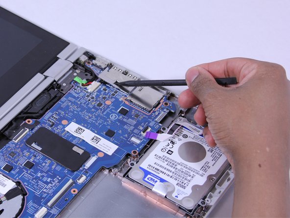
Disconnect the ribbon cables attached to the system board (motherboard).
-
Using the Heavy-Duty Spudger lift up the plastic locks connecting the ribbon cable to the motherboard.
-
Use the plastic tab on the ribbon cable to pull it out from the lock on the motherboard.
-
-
Este passo não foi traduzido. Ajude a traduzi-lo
-
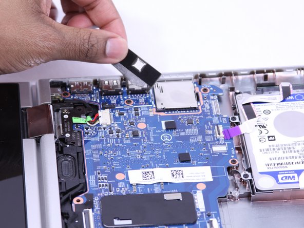
Disconnect the fastened cables from the system board (motherboard) by carefully pushing the cable's plastic edges using the Heavy Duty Spudger.
-
-
Este passo não foi traduzido. Ajude a traduzi-lo
-
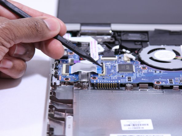
Pull the clipped cables from system board (motherboard).
-
-
Este passo não foi traduzido. Ajude a traduzi-lo
-
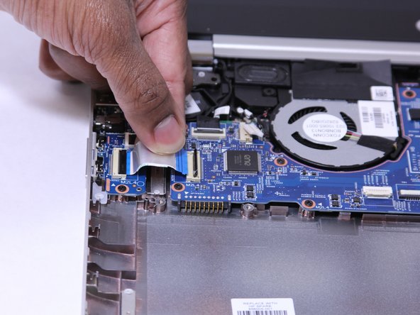
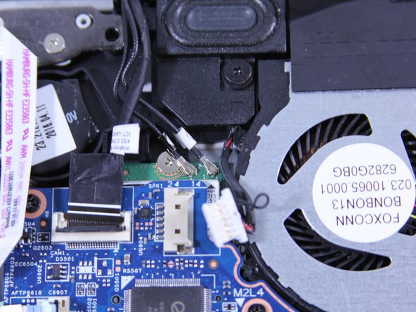
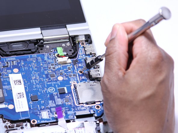
Remove the system board (motherboard).
-
Using the Phillips 00 Screw Driver, remove 9 Phillips 2.0 x 4.7 mm screws with "M2L4" next to them.
-
Using the Phillips 00 Screw Driver, remove the silver screw.
-
-
Este passo não foi traduzido. Ajude a traduzi-lo
-
Using a Heavy Duty Spudger, disconnect the black and red RTC battery cable on the left side of the system board (motherboard).
-
-
Este passo não foi traduzido. Ajude a traduzi-lo
-
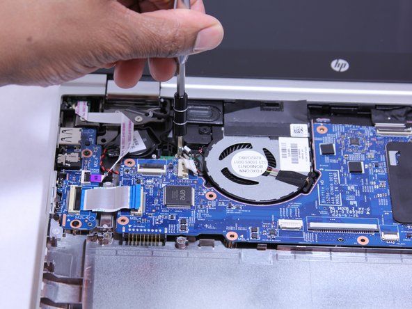
Release the system board (motherboard) from the base enclosure.
-


Cancelar: não concluí este guia.
3 outras pessoas executaram este guia.

Equipe

UW Tacoma, Team 1-6, Rose Winter 2017 Membro de UW Tacoma, Team 1-6, Rose Winter 2017
UWT-ROSE-W17S1G6
Membros da 4
Autoria de 8 guias