Esta versão pode conter edições incorretas. Mude para o último instantâneo verificado.
O que você precisa
-
Este passo não foi traduzido. Ajude a traduzi-lo
-
Flip your device over so the bottom panel is facing up.
-
-
Este passo não foi traduzido. Ajude a traduzi-lo
-
The battery is held in by a latch in the front and tabs in the back.
-
Slide the lock switch left, towards the center of the computer.
-
Lift up the battery, rotating it up and away from you, then pull it out.
-
-
Este passo não foi traduzido. Ajude a traduzi-lo
-
Use a Phillips #1 screw driver to unscrew the black 4 mm Phillips #1 screw on the wireless card.
-
-
Este passo não foi traduzido. Ajude a traduzi-lo
-
Use a plastic opening tool to lift the wireless card out of its slot.
-
-
Este passo não foi traduzido. Ajude a traduzi-lo
-
Pull the black and white wires up and off of the wireless card.
-
Remove the wireless card.
-
-
Este passo não foi traduzido. Ajude a traduzi-lo
-
Unscrew the 7 mm Phillips #1 screw next to the keyboard icon.
-
-
-
Este passo não foi traduzido. Ajude a traduzi-lo
-
Carefully pry up one of the top corners of the keyboard with a prying tool. Slide the tool along the top of the keyboard to release it from the housing. Pull the top of the keyboard towards you an inch or two.
-
Pull the keyboard up and away from you, as it is held in by clips in the front. It is not yet disconnected.
-
-
Este passo não foi traduzido. Ajude a traduzi-lo
-
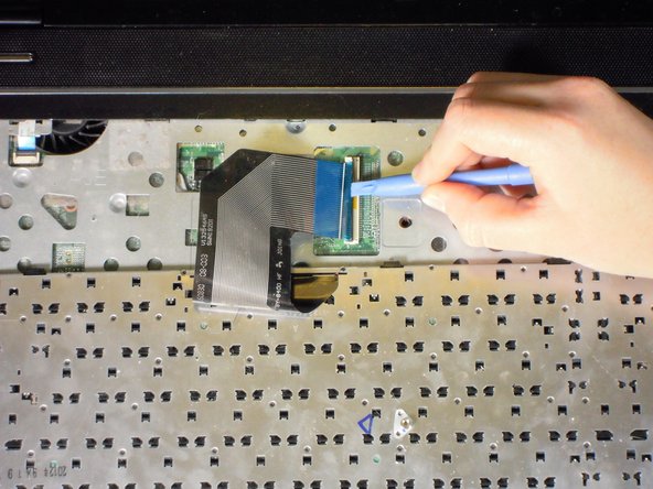
Gently turn keyboard over, towards you, to reveal the silver cable ribbon.
-
-
Este passo não foi traduzido. Ajude a traduzi-lo
-
Using a prying tool, flip the black clip up and to the right. Pull the silver cable out and to the left, the keyboard is now detached from the laptop.
-
-
Este passo não foi traduzido. Ajude a traduzi-lo
-
Unscrew the four 7 mm Phillips #1 screws on the board.
-
-
Este passo não foi traduzido. Ajude a traduzi-lo
-
Use a plastic opening tool to lift the white clip up, towards the screen.
-
Pull the white cable with blue head, away from the clip.
-
-
Este passo não foi traduzido. Ajude a traduzi-lo
-
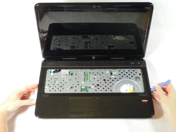
With a plastic opening tool, pry open a side or corner of the top panel. Slide the tool around the rest of the panel to release it from the clips.
-
-
Este passo não foi traduzido. Ajude a traduzi-lo
-
Rotate the top panel away from you, keeping the back near the hinge of the laptop to avoid damaging the speaker cable.
-
-
Este passo não foi traduzido. Ajude a traduzi-lo
-
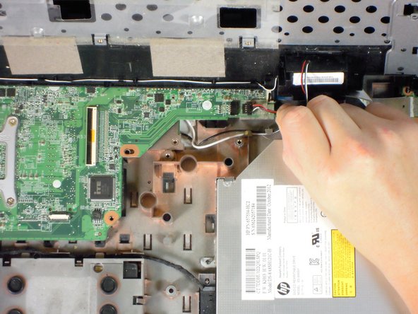
Using a plastic opening tool, disconnect the black speaker connector from the top right of the motherboard.
-
Set aside the top panel until your are ready to reassemble your laptop.
-
-
Este passo não foi traduzido. Ajude a traduzi-lo
-
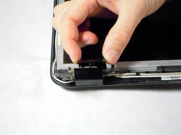
In the top left hand corner, disconnect the monitor cable from the motherboard by pulling up on the black tab.
-
-
Este passo não foi traduzido. Ajude a traduzi-lo
-
Unscrew the four black 7 mm Phillips #1 screws that attach the hinges to the case.
-
Remove the screen assembly from the laptop.
-
-
Este passo não foi traduzido. Ajude a traduzi-lo
-
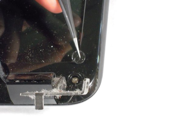
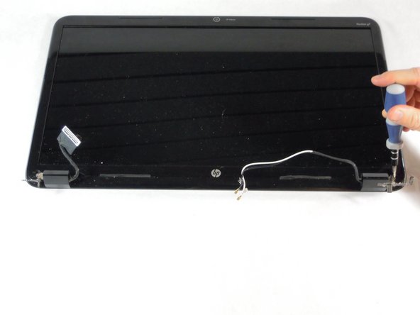
Using tweezers, remove the two screw covers at the bottom of the screen.
-
Unscrew the two 6 mm Phillips #1 screws from the bottom of the screen.
-
-
Este passo não foi traduzido. Ajude a traduzi-lo
-
Firmly pry the front screen cover off. Slide the prying tool around the front screen.
-
-
Este passo não foi traduzido. Ajude a traduzi-lo
-
Unscrew the six 5 mm Phillips #1 screws.
-
Remove the two black hinge covers.
-
-
Este passo não foi traduzido. Ajude a traduzi-lo
-
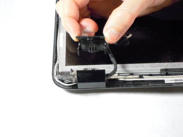
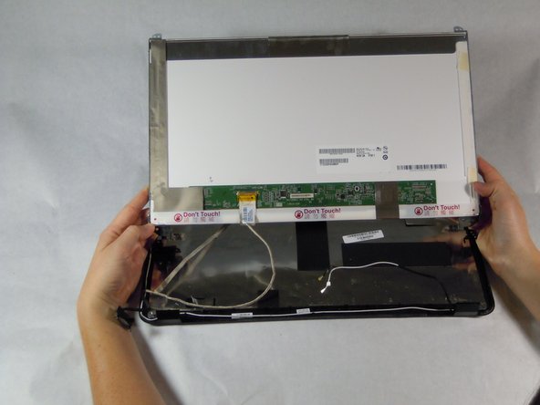
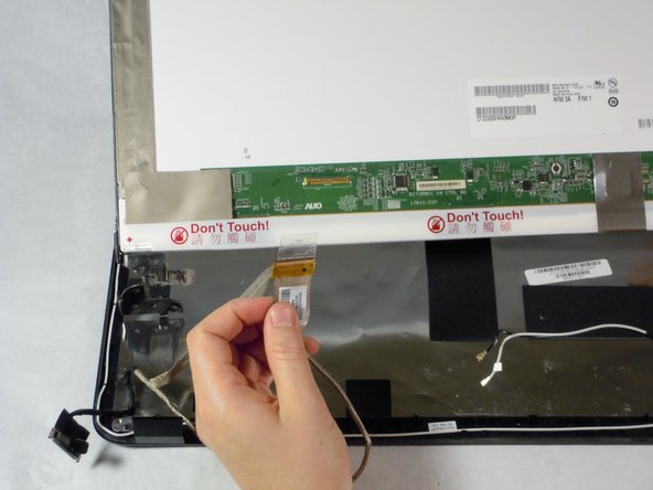
Gently remove the screen from its housing. Turn the screen over (parallel to you) and disconnect the webcam cable.
-
Separate the webcam cable from the screen.
-
-
Este passo não foi traduzido. Ajude a traduzi-lo
-
Remove the four 4 mm Phillips #1 screws from the sides of the screen.
-
Remove the two hinge assemblies.
-


Cancelar: não concluí este guia.
20 outras pessoas executaram este guia.

Equipe

Cal Poly, Team 11-51, Amido Spring 2014 Membro de Cal Poly, Team 11-51, Amido Spring 2014
CPSU-AMIDO-S14S11G51
Membros da 4
Autoria de 21 guias
2 comentários
or you could just pop of the plastic bezel and unscrew the LCD and then unplug the screen from the back and be done with it. You made way more work for yourself then what is needed.
Thank you for this guide! I was working on a screen replacement for an HP G7-1260us, but it was built so similarly to the one in your guide that I was able to follow the guide and successfully replace the screen.