Esta versão pode conter edições incorretas. Mude para o último instantâneo verificado.
O que você precisa
-
Este passo não foi traduzido. Ajude a traduzi-lo
-
Turn the computer off and disconnect if from all power sources.
-
-
Este passo não foi traduzido. Ajude a traduzi-lo
-
Hold the release switch all of the way to the left and your other hand to pull the battery out.
-
-
Este passo não foi traduzido. Ajude a traduzi-lo
-
Remove service hatch by sliding away from the computer and lifting up.
-
-
Este passo não foi traduzido. Ajude a traduzi-lo
-
Push the retraining springs away from the RAM at the same time to unlock the RAM.
-
-
-
Este passo não foi traduzido. Ajude a traduzi-lo
-
Pull the RAM out.
-
Follow the same procedure for the additional RAM.
-
-
Este passo não foi traduzido. Ajude a traduzi-lo
-
Use the flat end of a spudger to pop off the antenna connectors.
-
-
Este passo não foi traduzido. Ajude a traduzi-lo
-
Remove single Phillips #00 screw.
-
Pull the card out by hand.
-
-
Este passo não foi traduzido. Ajude a traduzi-lo
-
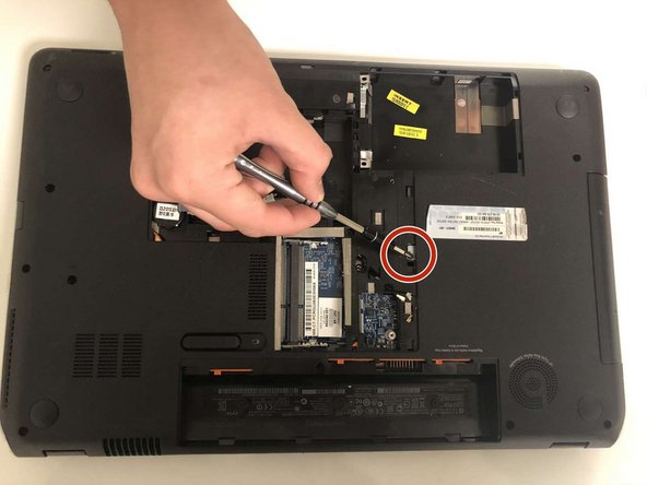
Remove the single Phillips #00 screw.
-
Flip the laptop over.
-
-
Este passo não foi traduzido. Ajude a traduzi-lo
-
Wedge a spudger in between the keyboard and the upper bezel (nearest the screen).
-
Pry upward to release the keyboard clips.
-
-
Este passo não foi traduzido. Ajude a traduzi-lo
-
Use the flat end of a spudger to flip up the black tab on the ZIF connectors.
-
Pull the ribbon cables out of the ZIF connectors.
-
Remove the keyboard.
-
-
Este passo não foi traduzido. Ajude a traduzi-lo
-
Flip the keyboard back over.
-
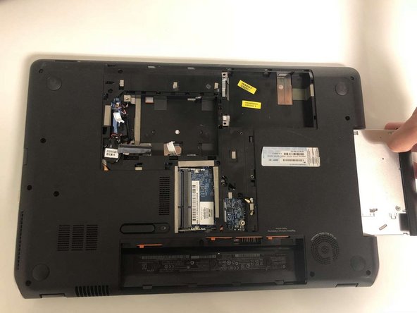
Remove the single Phillips #00 screw holding in the CD drive.
-
Pull out the CD drive.
-
-
Este passo não foi traduzido. Ajude a traduzi-lo
-
Remove the seventeen Phillips #00 screws securing the back panel to the laptop.
-
-
Este passo não foi traduzido. Ajude a traduzi-lo
-
Flip the laptop over.
-
Remove the single Phillips #00 screw.
-


Equipe

University of North Texas, Team S1-G1, Thompson Spring 2018 Membro de University of North Texas, Team S1-G1, Thompson Spring 2018
UNT-THOMPSON-S18S1G1
Membros da 6
Autoria de 11 guias