Esta versão pode conter edições incorretas. Mude para o último instantâneo verificado.
O que você precisa
-
Este passo não foi traduzido. Ajude a traduzi-lo
-
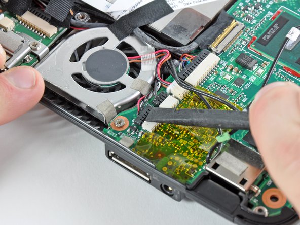
Use the flat end of a spudger or your fingers to disconnect the following cables:
-
Speaker cable
-
Microphone cable
-
Fan cable
-
Power cable
-
Display data cable
-
-
-
Este passo não foi traduzido. Ajude a traduzi-lo
-
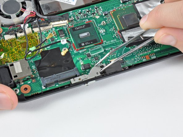
Remove the 2.5 mm Phillips screw securing the power switch lever to the lower case.
-
Use a pair of tweezers or your fingers to lift the power switch lever out of the Mini 1000.
-
-
Este passo não foi traduzido. Ajude a traduzi-lo
-
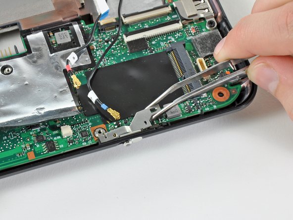
Remove the 2.5 mm Phillips screw securing the wireless on/off switch lever to the lower case.
-
Use tweezers or your fingers to remove the wireless on/off switch lever from the Mini 1000.
-
-
Este passo não foi traduzido. Ajude a traduzi-lo
-
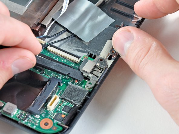
Remove the two 3 mm Phillips screws securing the USB bracket to the lower case.
-
Pry up the USB bracket and remove it from the motherboard.
-
-
Este passo não foi traduzido. Ajude a traduzi-lo
-
Remove the single 4.5 mm Phillips screw securing the motherboard to the lower case near the fan.
-
-
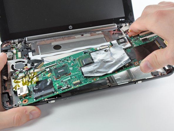
Este passo não foi traduzido. Ajude a traduzi-lo
-
Carefully lift the motherboard from its right edge and remove it from the lower case, minding any cables that may get caught.
-